
Instruction manual


SECTION 8. FILES, PROTOCOLS, AND UTILITIES
8-4
Limitations and issues of concern to the client
application include:
1. Each record must be acknowledged before
the next record will be sent.
2. Records will occasionally be transferred out
of time sequential order.
3. The same record may be transferred
multiple times.
4. When a session breaks, the server's
buffering is limited and may ultimately
depend on buffering in the datalogger and
re-collection to provide as many records as
possible when the session is re-connected.
The record acknowledgment allows the server
to make sure that every record that it intended
to send was successfully received by the client.
This capability, coupled with reasonable
algorithms that make sure every record logged
by the datalogger is received by the server,
allows for reliable data collection.
Records are occasionally sent out of time
sequential order because 1) it allows real time
monitoring to take priority over the collection of
older data missed due to communication
failures, and 2) the user can initiate the
collection (or re-collection) of any records still
buffered in the datalogger. It is hard to predict
just how "out of order" records will get, but
usually, once network communication is stable,
records will come in order and as close to real
time as possible.
There are two reasons why records may be
sent multiple times. First, the server application
is shut down, then brought back up, and
second, the user initiated the re-collection of
records from the datalogger. The mechanisms
used to verify that all records are sent are state
oriented. If the server is shut down in the wrong
state, some states will be repeated, thus
causing the same records to be sent multiple
times. If the initialization files were erased from
disk, then all records still buffered in
dataloggers may be sent again.
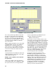
Client and server state diagrams are shown in
Figures 8.5-11 and 8.5-12 that document the
states and activities of the client and server
programs. These diagrams are applicable to
either Named Pipe or Socket implementations.
The diagramming notation is by Booch
1
who
claims to have adopted it from Harel
2
.
FIGURE 8.5-1. Client State Diagram