
Instruction manual


SECTION 5. NETADMIN
5-5
Direct Connect (SC32A) − Each remote data-
logger is entered as a node (child node of PC1).
No other nodes are necessary. Each data-
logger (each on its own serial port) has its own
polling interval.
Phone Modem (DC112) − Enter a node for the
phone modem at the computer site (phone-
base). Each remote datalogger will be entered
as a child node of the phone-base node. Each
remote will have its own polling interval with no
polling interval for the phone-base. See Section
4.1.2 for more information on scheduling.
RF (radio frequency) − Enter a node for the
RF232T (RF base station) as a child of the
computer. The polling interval is entered for the
base and will be used to poll all the dataloggers
that communicate with the base.
NOTE: For RF Radio frequency, poll at
least every 20 minutes.
Repeater only sites (no CR10T) are not entered as
nodes. Enter a node for each remote datalogger.
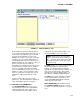
To use a repeater (either a repeater only site or a
CR10T/ RF95T site), enter the communication
path as part of the node description for the site
being communicated with. Enter the communi-
cation path in the VIA RF network parameter as a
series of repeater IDs separated by commas. End
the string with the ID of the remote site. For sites
not using repeaters, just enter the ID of the remote
RF95T as the VIA RF network parameter. A
RF95T ID is determined by its switch settings. See
the RF manual for infor-mation on how to set the
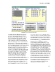
switches. In Figure 5-2, a remote site (station
name of Logan) has its switches set as ID 1. The
communication path is through a repeater with the
switches as ID 4.
Multidrop (MD9) − Set the base MD9 address to
255 and set each remote so the addresses are
unique. Enter a node for the base MD9. Enter the
remote nodes as children of this node. Enter the
address (switch setting) for each remote in the VIA
MD9 parameter. See the MD9 manual for infor-
mation on setting the switches. Each remote
CR10T will have its own polling interval.
Phone to RF or Phone to MD9 − Enter a node for
the phone modem. Enter Phone to RF base or
Phone to MD9 base as a child of this node. The
remote sites are children of this node. Phone to RF
and Phone to MD9 with measurement capability (a
CR10T at the site) is NOT supported by RTMS.
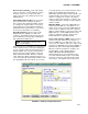
When the network description is complete, save
the description. Next select the option to
MAKE THE OPEN NET DESCRIPTION
ACTIVE. Both options (save and make active)
are found under the FILE selection on the main
menu. The status line at the bottom will confirm
these actions. This window can now be closed.
FIGURE 5-2. Editing a Sample RF Network