
User manual


Hukseflux Thermal Sensors
HFP01SC Manual v0811 page 28/33
9 Electrical connection of
HFP01SC
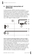
In order to operate, HFP01SC should be connected to a
measurement and control system as described above. A typical
connection is shown in figure 9.1. For the purpose of making a
correct measurement of the heater power there is a current
sensing resistor in the wire that leads to the heater. The voltage
over a 10-ohm current sensing resistor should be of the order of
magnitude of 1 to 2 Volts. The required resistance must be
0.1%, 50ppm or better. We recommend to use a value of 10
ohm, 0.1%, 50ppm, 0.6 Watt or similar.
Figure 9.1 electrical connection HFP01SC. Sensor (2) wiring 1
and 2. Heater (1) heater voltage input wires 3 and 4. Heater
current measurement, typically performed by putting a 10 ohm
resistor (3) in series, and by measuring the voltage across the
resistor, wires 5 and 6. Dashed line (4), sensor on the left and
cable and datalogger on the right.
A relay should be used to switch the heater on and off. The heat
flux plate output usually is connected to a differential voltage
input. The voltage across the current sensing resistor is also
measured by a differential voltage channel. HFP01SC has two
separate cables, one for the signal and one for the heater. The
colour codes can be found on the calibration certificate.
NOTE: the resistor is normally not part of the delivery.