
User manual


Hukseflux Thermal Sensors
HFP01SC Manual v0811 page 23/33
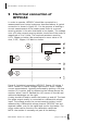
5 Putting HFP01SC into operation
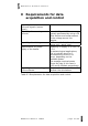
It is recommended to test the sensor functionality by checking
the impedance of the sensor and heater, and by checking if the
sensor works, according to the following table: (estimated time
needed: 20 minutes)
Check the connection of the heater. Use
a multimeter at the 200 ohms range.
Measure between two wires that are
connected to the heater. The typical
impedance of the wiring is 0.1 ohm/m.
Typical impedance should be 1.5 ohm
for the total resistance of two wires
(back and forth) of each 5 meters, plus
the heater resistance that is indicated
on the calibration certificate.
Infinite indicates a
broken circuit; zero
indicates a short circuit.
Expected value around
110 Ohms.
Warning: during this part of the test,
please put the sensor in a thermally
quiet surroundin
g
because a sensor that
generates a significant signal will
disturb the measurement.
Check the impedance of the sensor. Use
a multimeter at the 10 ohms range.
Measure at the sensor output first with
one polarity, than reverse polarity. Take
the average value.
The typical impedance
of the wiring is 0.1
ohm/m. Typical
impedance should be
1.5 ohm for the total
resistance of two wires
(back and forth) of
each 5 meters, plus the
typical sensor
impedance of between
2 and 5 ohms. Infinite
indicates a broken
circuit; zero indicates a
short circuit.
Check if the sensor reacts to heat flux.
Use a multimeter at the millivolt range.
Measure at the sensor output. Generate
a signal by touching the thermopile hot
joints (red side) with your hand.
The thermopile should
react by generating a
millivolt output signal.
If possible put a voltage to the heater
between 9 and 12 Volt to see the heater
functionality.
The thermopile should
react by generating a
millivolt output signal.
Table 5.1 Checking the functionality of the sensor. The procedure
offers a simple test to get a better feeling how HFP01SC works,
and a check if the sensor is OK.