
User manual


Hukseflux Thermal Sensors
HFP01SC Manual v0811 page 21/33
Response time
(nominal)
± 3 min (equals average soil)
Range + 2000 to - 2000 W.m
-2
Non stability < 1% change per year (normal
meteorological use)
compensated during self-calibration
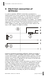
Required readout /
hardware
1.1 one differential voltage channel
or possibly (less ideal)
1.2 one single ended voltage channel.
When using more than one sensor and
having a lack of input channels, it can
be considered to put several sensors in
series, while working with the average
sensitivity.
2 one current measurement (typically
realised using a voltage measurement
across a 10 ohm resistor.
3 one Relay and timer to switch 12V,
0.1 A power to the heater.
Expected voltage
output
Meteorology: -10 to 20 mV (sensor),
0 to 2 V (heater current measuerment)
Heater resistance, area
90 - 110 ohm, 0.003885 m2
Voltage input (heater) 9-15 VDC (nominal), switched
Sensor resistance 2 Ohm (nominal) plus cable resistance
Heating power 1.5 W typically during 180 s, typically
every 3 or 6 hours
Power consumption Average 0.02 (3 hr) or 0.04 (6hr) W
Required programming
ϕ = V
sen
/ E
sen
Sensor dimensions 80 mm diameter, 5 mm thickness
Cable length, diameter 5 meters, 5 mm, 2 cables
Weight including 5 m
cable, transport dim.
0.3 kg
transport dimensions 32x23x3 cm
CALIBRATION
Calibration traceability to the “guarded hot plate” of National
Physical Laboratory (NPL) of the UK.
Applicable standards are ISO 8302 and
ASTM C177.
Recalibration interval Not applicable
OPTIONS
Extended cable Additional cable length x metres (add to
5m)
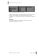
Table 4.1 List of HFP01SC specifications. (started on previous
page)