
User manual


Hukseflux Thermal Sensors
HFP01SC Manual v0811 page 14/33
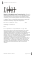
Figure 1.3.2 electrical connection HFP01SC. Sensor (2) wiring 1
and 2. Heater (1) heater voltage input wires 3 and 4. Heater
current measurement, typically performed by putting a 10 ohm
resistor (3) in series (not included with HFP01SC), and by
measuring the voltage across the resistor, wires 5 and 6. Dashed
line (4), sensor on the left and cable and datalogger on the right.
Figure 1.3.3 An alternative "short cut", explaining the working
principle of HFP01SC: in the self-calibrating heat flux plate, a
heater is incorporated. The reaction to a pulse in heating
represents the currently valid calibration constant. This principle
is valid in all environments, and eliminates errors due to the
thermal conductivity of the environment (soil moisture) and
temperature. In reality, the heat fluxes will deviate from 50%.
For calculation of the heat flux in the surrounding medium
however, the 50% -50% division remains valid.