
User manual


Hukseflux Thermal Sensors
HFP01SC Manual v0811 page 13/33
1.3 Self-calibration
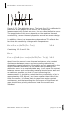
Figure 1.3.1 Explanation of the self-calibrating principle: On the
left the normal situation with a heat flux
ϕ
. Due to the fact that
sensor and medium do not match, the actual flux through the
sensor is reduced by a factor (1-X). This error is called deflection
error. On the right, the film heater that is mounted on top (1) is
activated to generate a well known heat flux
ϕ
. The response of
the heat flux sensor is measured. In the ideal situation 50% of
the generated flux
ϕ
would pass through the plate (typically 150
W/m
2
). In case of non matching thermal conductivities, a
deviation (X) will occur. The essence of this approach is that the
flow is divided in an upward flow through undisturbed medium
(1+X) and a downward flow through the heat flux sensor (a
disturbance) plus underlying medium. The (1-X) signal level
however, still represents a 0.5
ϕ
heat flux level of the normal
situation of the picture on the left. In other words, the
comparison of the measured heat flux to the total artificially
generated heat flow is used to correct for the deflection error.