
Specifications
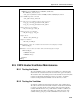
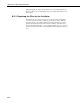
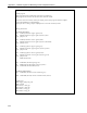
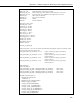

Table Of Contents
- Revision and Copyright Information
- Warranty and Assistance
- Table of Contents
- CNR4 Net Radiometer
- 1. General Description
- 2. Sensor Specifications
- 3. Installation
- 4. Using the Optional CNF4 Heater/Ventilator Unit
- 5. Using the CNR4 in the Four Separate Components Mode
- 5.1 Measuring Short-wave Solar Radiation with Pyranometer
- 5.2 Measuring Long-wave Far Infrared Radiation with Pyrgeometer
- 5.3 Measuring CNR4 Temperature with Thermistor
- 5.4 Calculation of Albedo
- 5.5 Calculation of Net Short-wave Radiation
- 5.6 Calculation of Net Long-wave Radiation
- 5.7 Calculation of Net (Total) Radiation
- 6. Wiring
- 7. Datalogger Programming
- 8. Troubleshooting
- 9. Maintenance and Recalibration
- Appendix A. CNR4 Performance and Measurements under Different Conditions
- Appendix B. CNF4 Heater/Ventilator
- Appendix C. CR3000 Program for Measuring Pt-100 Temperature Sensor
- Campbell Scientific Contact Information

Appendix B. CNF4 Heater/Ventilator
'CNR4 thermistor measurement
BrHalf (Vs_Vx,1,mv5000,16,Vx1,1,2500,True ,0,250,1.0,0)
Rs = 1000*(Vs_Vx/(1-Vs_Vx))
cnr4_T_C = 1/(1.0295e-3+2.391e-4*LN(Rs)+1.568e-7*(LN(Rs))^3)-273.15
'Convert CNR4 temperature to Kelvin
cnr4_T_K = cnr4_T_C+273.15
'Correct the long-wave radiation values from pyrgeometers
long_up_corr = long_up+5.67e-8*cnr4_T_K^4
long_dn_corr = long_dn+5.67e-8*cnr4_T_K^4
'Compute short-wave net radiation
Rs_net = short_up - short_dn
'Compute long-wave net radiation
Rl_net = long_up - long_dn
'Compute albedo
albedo = short_dn/short_up
'Compute net radiation
Rn = Rs_net + Rl_net
'CNF4 ventilator control - the ventilator will be turned on when flag(1) is set high
SW12 (1,flag(1))
'CNF4 heater control - the heater will be turned on when flag(2) is set high
SW12 (2,flag(2))
CallTable cnr4_data
CallTable cnr4_ts
NextScan
EndProg
B.5 CNF4 Heater/Ventilator Maintenance
B.5.1 Testing the Heater
The optional CNF4 consists of a heater and a ventilator. To check the heater
unit, measure the resistance between the two heater wires (green and yellow).
The resistance value of the heating resistor inside should be around 15 Ω (cable
resistance should add about 0.026 Ω per each foot of cable). An infinite
resistance reading indicates the likelihood of a broken wire, or cable.
B.5.2 Testing the Ventilator
To check the ventilator, first measure the impedance of the ventilator motor.
The value should be around 30 Ω (cable resistance should add about 0.026 Ω
per each foot of cable). If the correct resistance value is measured, but the
ventilator still mal-functions, it is possible that the ventilator is stalled by an
object blocking the fan. Remove the black cover at the bottom side of the
ventilator unit, by prying it open with a small flat-head screw driver or by
B-11