
Specifications
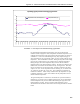
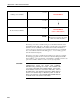
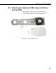
Table Of Contents
- Revision and Copyright Information
- Warranty and Assistance
- Table of Contents
- CNR4 Net Radiometer
- 1. General Description
- 2. Sensor Specifications
- 3. Installation
- 4. Using the Optional CNF4 Heater/Ventilator Unit
- 5. Using the CNR4 in the Four Separate Components Mode
- 5.1 Measuring Short-wave Solar Radiation with Pyranometer
- 5.2 Measuring Long-wave Far Infrared Radiation with Pyrgeometer
- 5.3 Measuring CNR4 Temperature with Thermistor
- 5.4 Calculation of Albedo
- 5.5 Calculation of Net Short-wave Radiation
- 5.6 Calculation of Net Long-wave Radiation
- 5.7 Calculation of Net (Total) Radiation
- 6. Wiring
- 7. Datalogger Programming
- 8. Troubleshooting
- 9. Maintenance and Recalibration
- Appendix A. CNR4 Performance and Measurements under Different Conditions
- Appendix B. CNF4 Heater/Ventilator
- Appendix C. CR3000 Program for Measuring Pt-100 Temperature Sensor
- Campbell Scientific Contact Information
Appendix B. CNF4 Heater/Ventilator
B.3 Wiring
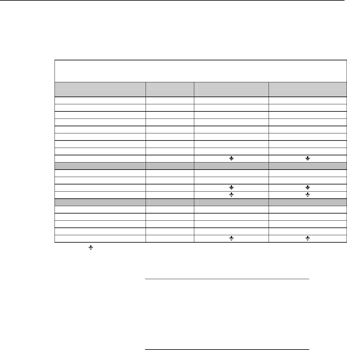
The following table shows the recommended datalogger wiring for using the
CNR4 sensor with the CNF4 heater/ventilator while making the differential
measurement.
TABLE B-1. CR1000 and CR3000 Datalogger Connections for Differential Measurement with
Heater/Ventilator Control
Function Wire Color CR1000 CR3000
Pyranometer Up Signal Red Differential Input (H) Differential Input (H)
Pyranometer Up Reference *Blue Differential Input (L) Differential Input (L)
Pyranometer Down Signal White Differential Input (H) Differential Input (H)
Pyranometer Down Reference *Black Differential Input (L) Differential Input (L)
Pyrgeometer Up Signal Grey Differential Input (H) Differential Input (H)
Pyrgeometer Up Reference *Yellow Differential Input (L) Differential Input (L)
Pyrgeometer Down Signal Brown Differential Input (H) Differential Input (H)
Pyrgeometer Down Reference *Green Differential Input (L) Differential Input (L)
Shield Clear
Thermistor
Thermistor Signal White Single-ended Input Single-ended Input
Thermistor Voltage Excitation Red Voltage Excitation (VX) Voltage Excitation (VX)
Thermistor Signal Reference Black
Shield Clear
CNF4 Heater/Ventilator
Ventilator Power Red SW12V SW12V-1
Ventilator Ground Blue G G
Heater Power Green SW12V SW12V-2
Heater Ground Yellow G G
Shield Clear
*Jumper to with user supplied wire
*Pull back wires for Pt-100 (grey, brown, green, and yellow), which are not in use, and tie them around the TEMP
cable using a cable tie or electrical tape to avoid possible damage to the Pt-100, due to electrical short circuit.
Do not use the SW12 channel of a CR1000 or CR3000 to
simultaneously power the heater and ventilator.
Simultaneously powering the heater and ventilator will
exceed the current limit of the SW12 channel. If the heater
and ventilator need to be used at the same time, connect
the CNF4 to the 12V channel instead of the SW12 channel
and use an external relay to switch the power on and off.
Refer to Section 4.1 of the CR1000 and CR3000 manual
for details on the 12V current source limits.
CAUTION
B-7