
Specifications
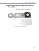
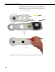
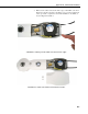
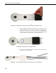
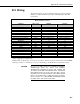
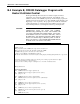
Table Of Contents
- Revision and Copyright Information
- Warranty and Assistance
- Table of Contents
- CNR4 Net Radiometer
- 1. General Description
- 2. Sensor Specifications
- 3. Installation
- 4. Using the Optional CNF4 Heater/Ventilator Unit
- 5. Using the CNR4 in the Four Separate Components Mode
- 5.1 Measuring Short-wave Solar Radiation with Pyranometer
- 5.2 Measuring Long-wave Far Infrared Radiation with Pyrgeometer
- 5.3 Measuring CNR4 Temperature with Thermistor
- 5.4 Calculation of Albedo
- 5.5 Calculation of Net Short-wave Radiation
- 5.6 Calculation of Net Long-wave Radiation
- 5.7 Calculation of Net (Total) Radiation
- 6. Wiring
- 7. Datalogger Programming
- 8. Troubleshooting
- 9. Maintenance and Recalibration
- Appendix A. CNR4 Performance and Measurements under Different Conditions
- Appendix B. CNF4 Heater/Ventilator
- Appendix C. CR3000 Program for Measuring Pt-100 Temperature Sensor
- Campbell Scientific Contact Information
Appendix B. CNF4 Heater/Ventilator
FIGURE B-5. Attaching the solar shield to CNF4 using four flat-head screws.
4. Once the CNF4 heater/ventilator unit is attached to the bottom side of the
CNR4, the CNF4 will cover the label that contains the serial number and
the sensitivity values for the four sensors. Affix the extra label that came
with the sensor to the bottom side of the CNF4’s anodized aluminium base
so that the label is in a visible location. See Figure B-6 below.
FIGURE B-6. Affixing the sensor label to CNF4.
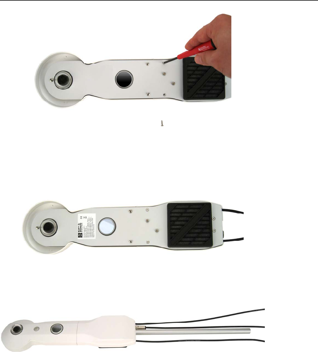
5. Connect the heater/ventilator power control cable and the mounting rod to
the CNF4, as shown in Figure B-7.
FIGURE B-7. Connecting the CNF4 power control cable and the mounting rod.
B-6