
Specifications

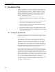

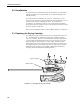
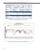
Table Of Contents
- Revision and Copyright Information
- Warranty and Assistance
- Table of Contents
- CNR4 Net Radiometer
- 1. General Description
- 2. Sensor Specifications
- 3. Installation
- 4. Using the Optional CNF4 Heater/Ventilator Unit
- 5. Using the CNR4 in the Four Separate Components Mode
- 5.1 Measuring Short-wave Solar Radiation with Pyranometer
- 5.2 Measuring Long-wave Far Infrared Radiation with Pyrgeometer
- 5.3 Measuring CNR4 Temperature with Thermistor
- 5.4 Calculation of Albedo
- 5.5 Calculation of Net Short-wave Radiation
- 5.6 Calculation of Net Long-wave Radiation
- 5.7 Calculation of Net (Total) Radiation
- 6. Wiring
- 7. Datalogger Programming
- 8. Troubleshooting
- 9. Maintenance and Recalibration
- Appendix A. CNR4 Performance and Measurements under Different Conditions
- Appendix B. CNF4 Heater/Ventilator
- Appendix C. CR3000 Program for Measuring Pt-100 Temperature Sensor
- Campbell Scientific Contact Information

CNR4 Net Radiometer
8. Troubleshooting
If there is no indication as to what may be the problem, start performing the
following "upside-down test", which is a rough test for a first diagnosis. It can
be performed both outdoors and indoors. Indoors, a lamp can be used as a
source for both short-wave and long-wave radiation. Outdoors, one should
preferably work with a solar elevation of more than 45 degrees (45 degrees
above horizon) and under stable conditions (no large changes in solar
irradiance, and preferably no clouds).
1. Measure the radiation outputs in the normal position. Record the
measured values when the signals have stabilized, i.e. after about three
minutes.
2. Rotate the instrument 180 degrees, so that the upper and the lower sensors
are now in the reverse orientation as to the previous position.
3. Measure the radiation outputs once more. Record the measured values
when the radiometers have stabilized.
4. The computed net radiation values in rotated position should be equal in
magnitude but only differing in sign. In a rough test like this, deviations
of ± 10 % can be tolerated. If deviations greater than this are encountered,
the following tests might help.
8.1 Testing the Pyranometer
As a first test, check the sensor impedance. It should have a nominal value as
indicated in the specifications. Zero, or infinite resistance, indicates a failure in
hardware connection.
Before starting the second test measurement, let the pyranometer rest for at
least five minutes to let it regain its thermal equilibrium. For testing, set a
voltmeter to its most sensitive range setting. Darken the sensor. The signal
should read zero. Bear in mind that the response takes about one minute.
Small deviations from zero are possible; this is caused by the thermal effects,
such as touching the pyranometer with your hand. This thermal effect can be
demonstrated by deliberately heating the pyranometer with your hand. If the
zero offset is within specifications, proceed with the third test.
In the third test the sensor should be exposed to light. The signal should be a
positive reading. Set the voltmeter range in such a way that the expected full-
scale output of the pyranometer is within the full-scale input range of the
voltmeter. The range can be estimated on theoretical considerations. When the
maximum expected radiation is 1500 W/m
2
, which is roughly equal to normal
outdoor daylight conditions, and the sensitivity of the pyranometer is 15 μV per
W/m
2
, the expected output range of the pyranometer is equal to 22500 μV, or
22.5 mV. One can calculate the radiation intensity by dividing the
pyranometer output as measured by the voltmeter (e.g. 22.5 mV) by the sensor
sensitivity (15 μV/W/m
2
). If no faults are found up to this point, your
pyranometer is probably doing fine.
28