
Specifications
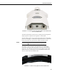
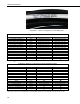
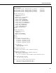

Table Of Contents
- Revision and Copyright Information
- Warranty and Assistance
- Table of Contents
- CNR4 Net Radiometer
- 1. General Description
- 2. Sensor Specifications
- 3. Installation
- 4. Using the Optional CNF4 Heater/Ventilator Unit
- 5. Using the CNR4 in the Four Separate Components Mode
- 5.1 Measuring Short-wave Solar Radiation with Pyranometer
- 5.2 Measuring Long-wave Far Infrared Radiation with Pyrgeometer
- 5.3 Measuring CNR4 Temperature with Thermistor
- 5.4 Calculation of Albedo
- 5.5 Calculation of Net Short-wave Radiation
- 5.6 Calculation of Net Long-wave Radiation
- 5.7 Calculation of Net (Total) Radiation
- 6. Wiring
- 7. Datalogger Programming
- 8. Troubleshooting
- 9. Maintenance and Recalibration
- Appendix A. CNR4 Performance and Measurements under Different Conditions
- Appendix B. CNF4 Heater/Ventilator
- Appendix C. CR3000 Program for Measuring Pt-100 Temperature Sensor
- Campbell Scientific Contact Information
CNR4 Net Radiometer
FIGURE 6-2. The marks on the end of the CNR4: S for SOLAR cable,
and T for TEMP cable.
The measurement details for Pt-100 sensor, including the wiring diagram and
sample program are explained in the Appendix C of this manual.
The four radiation outputs can be measured using differential or single-ended
inputs on the datalogger. A differential voltage measurement is recommended
because it has better noise rejection than a single-ended measurement.
When differential inputs are used, jumper the low side of the
input to AG or to keep the signal in common mode range.
NOTE
The Tables 6-1 and 6-2 show the wiring instructions for the differential
measurement and single-ended measurement connections to the datalogger,
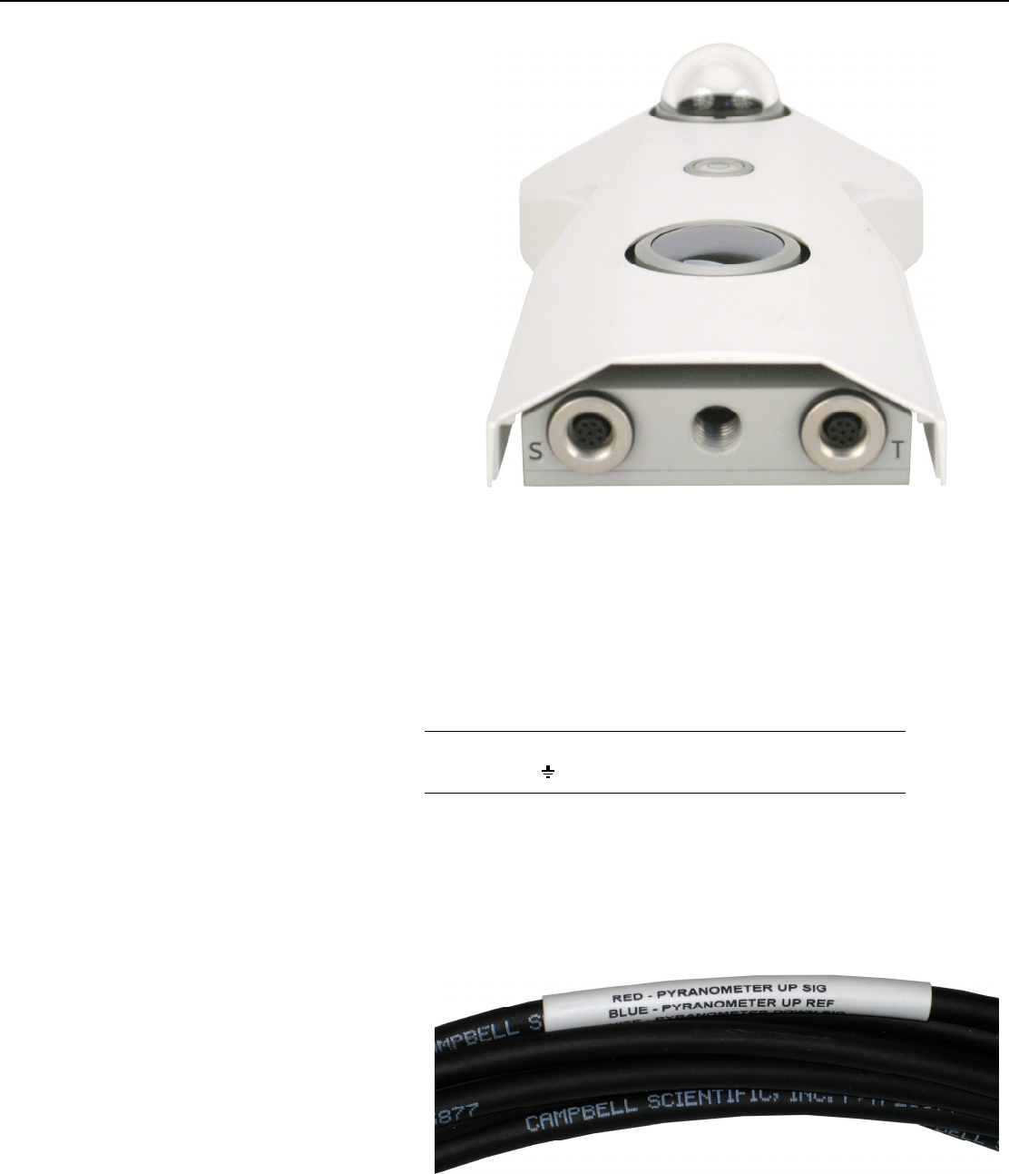
respectively. The cables have the white band at the pigtail end of the cable
with the color keys. See the Figure 6-3 and 6-4 below for the labels on the
cable for both the SOLAR and TEMP cables.
FIGURE 6-3. Labels on the pigtail end of the SOLAR cable.
15