
Specifications
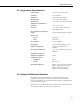
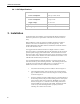
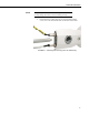
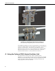
Table Of Contents
- Revision and Copyright Information
- Warranty and Assistance
- Table of Contents
- CNR4 Net Radiometer
- 1. General Description
- 2. Sensor Specifications
- 3. Installation
- 4. Using the Optional CNF4 Heater/Ventilator Unit
- 5. Using the CNR4 in the Four Separate Components Mode
- 5.1 Measuring Short-wave Solar Radiation with Pyranometer
- 5.2 Measuring Long-wave Far Infrared Radiation with Pyrgeometer
- 5.3 Measuring CNR4 Temperature with Thermistor
- 5.4 Calculation of Albedo
- 5.5 Calculation of Net Short-wave Radiation
- 5.6 Calculation of Net Long-wave Radiation
- 5.7 Calculation of Net (Total) Radiation
- 6. Wiring
- 7. Datalogger Programming
- 8. Troubleshooting
- 9. Maintenance and Recalibration
- Appendix A. CNR4 Performance and Measurements under Different Conditions
- Appendix B. CNF4 Heater/Ventilator
- Appendix C. CR3000 Program for Measuring Pt-100 Temperature Sensor
- Campbell Scientific Contact Information
CNR4 Net Radiometer
5.7 Calculation of Net (Total) Radiation
In the four separate components mode, net radiation, R
n
, can be calculated
using the individual sensor measurement results:
R
n
= {(E upper Pyranometer) - (E lower Pyranometer)}
+ {(E upper Pyrgeometer) - (E lower Pyrgeometer)} (5-8)
Where E upper/lower pyranometers are calculated according to Equation 5-1,
and E upper/lower pyrgeometers are calculated according to Equation 5-2. The
terms with T cancel each other out.
6. Wiring
The CNR4 has two outputs for short-wave radiation, two outputs for long-wave
radiation, thermistor output, and Pt-100 temperature sensor output. In addition,
if a user chooses to attach the optional CNF4 heater/ventilator unit, it will have
power wires for heater and ventilator. All wiring schemes shown in this
manual and the sample programs will use the thermistor for the temperature
measurement of the CNR4. The wiring diagrams for the thermistor in this
manual is applicable only if the CNR4 and the cables were purchased from
Campbell Scientific, Inc.
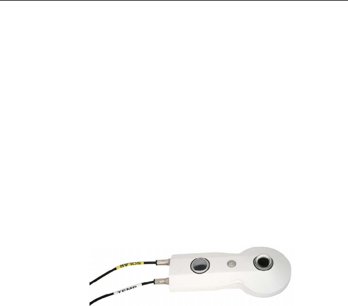
The CNR4 comes with two sets of cables labelled SOLAR and TEMP, as
shown in Figure 6-1. Figure 6-2 shows the marks by the connecting ports at
the sensor’s end for the cable connection: S and T for SOLAR and TEMP
cables, respectively. The two cables, SOLAR and TEMP, have identical
connectors, and care should be used to make sure that the correct cables are
connected to the correct ports of the sensor.
FIGURE 6-1. The CNR4 sensor with SOLAR and TEMP cables.
14