
Specifications
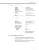
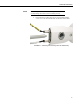
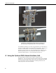
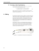
Table Of Contents
- Revision and Copyright Information
- Warranty and Assistance
- Table of Contents
- CNR4 Net Radiometer
- 1. General Description
- 2. Sensor Specifications
- 3. Installation
- 4. Using the Optional CNF4 Heater/Ventilator Unit
- 5. Using the CNR4 in the Four Separate Components Mode
- 5.1 Measuring Short-wave Solar Radiation with Pyranometer
- 5.2 Measuring Long-wave Far Infrared Radiation with Pyrgeometer
- 5.3 Measuring CNR4 Temperature with Thermistor
- 5.4 Calculation of Albedo
- 5.5 Calculation of Net Short-wave Radiation
- 5.6 Calculation of Net Long-wave Radiation
- 5.7 Calculation of Net (Total) Radiation
- 6. Wiring
- 7. Datalogger Programming
- 8. Troubleshooting
- 9. Maintenance and Recalibration
- Appendix A. CNR4 Performance and Measurements under Different Conditions
- Appendix B. CNF4 Heater/Ventilator
- Appendix C. CR3000 Program for Measuring Pt-100 Temperature Sensor
- Campbell Scientific Contact Information
CNR4 Net Radiometer
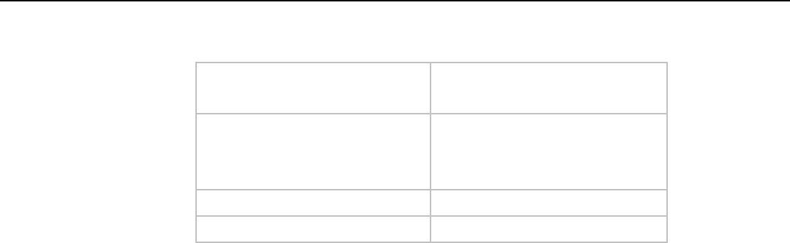
2.4.1 CNF4 Specifications
Heater
Power consumption:
10 W @ 12 Vdc (15 Ω)
Ventilator
Power consumption:
Supply voltage:
5 W @ 12 Vdc
8 to 13.5 Vdc
Weight:
1.11 lbs (0.5 kg)
Operating temperature:
-40 to +80°C
3. Installation
For measurement of net radiation, it is most important that the instrument is
located in a place that is representative of the entire area that one wishes to
study.
When installed on a mast, the preferred orientation should be such that no
shadow is cast on the net radiometer at any time during the day. In the
Northern Hemisphere this implies that the net radiometer should be mounted
on the south side of the mast.
It is suggested that the CNR4 is mounted at a height of at least 1.5 meters
above the surface to avoid shading effects of the instruments on the soil and to
promote spatial averaging of the measurement. If the instrument is h meters
above the surface, 99% of the input of the lower sensors comes from a circular
area with a radius of 10h. Shadows or surface disturbances with radius < 0.1h
will affect the measurement by less than 1%.
It is recommended that the CNR4 be mounted to a separate vertical pipe at
least 25 feet from any other mounting structures. The mounting bracket (CSI
p/n 26120) is used to mount the CNR4 directly to a vertical pipe, or to a
CM20x series Sensor Crossarm. Mount the sensor as follows:
1. First, attach the mounting rod to the CNR4, as shown in Figure 3-1.
2. Attach mounting bracket (CSI p/n 26120) to the vertical mounting
pipe or CM20x series Sensor Crossarm, using the U-bolts provided
as shown in Figure 3-2.
3. Insert the mounting rod of the CNR4 sensor into a mounting block of
the mounting bracket (CSI p/n 26120), making sure the sensor points
to the direction of the arrows marked as “SENSOR” on top of the
bracket (see Figure 3-2). Perform a coarse levelling of the sensor
using the bubble level on the top of the CNR4, and tighten the four
screws on top of the mounting bracket to properly secure the
mounting rod so that it does not rotate.
6