Wireless Sensor Network Revision: 9/11 C o p y r i g h t © 2 0 1 0 - 2 0 1 1 C a m p b e l l S c i e n t i f i c , I n c .
Warranty “PRODUCTS MANUFACTURED BY CAMPBELL SCIENTIFIC, INC. are warranted by Campbell Scientific, Inc. (“Campbell”) to be free from defects in materials and workmanship under normal use and service for twelve (12) months from date of shipment unless otherwise specified on the corresponding Campbell invoice. Batteries, fine-wire thermocouples, desiccant, and other consumables have no warranty.
Assistance Products may not be returned without prior authorization. The following contact information is for US and International customers residing in countries served by Campbell Scientific, Inc. directly. Affiliate companies handle repairs for customers within their territories. Please visit www.campbellsci.com to determine which Campbell Scientific company serves your country. To obtain a Returned Materials Authorization (RMA), contact CAMPBELL SCIENTIFIC, INC., phone (435) 227-2342.
Wireless Sensor Network Table of Contents PDF viewers note: These page numbers refer to the printed version of this document. Use the Adobe Acrobat® bookmarks tab for links to specific sections. 1. Understanding a Wireless Sensor Network ..............1 1.1 1.2 1.3 1.4 1.5 General Description ..................................................................................1 CWB100 Wireless Base Station ...............................................................2 CWS220 Wireless Infrared Radiometer ..
Wireless Sensor Network Table of Contents 3.2 Creating a Model of the WSN ............................................................... 16 3.2.1 Wireless Sensor Planner and Network Planner............................ 16 3.2.2 Installing Wireless Sensor Planner............................................... 17 3.2.3 Using Wireless Sensor Planner .................................................... 17 3.2.3.1 Simple WSN Example........................................................ 18 3.
Wireless Sensor Network Table of Contents B. Measurement Names and Meanings ..................... B-1 B.1 CWS220 Default Names......................................................................B-1 B.2 CWS655 Default Names......................................................................B-1 B.3 CWS900 Default Names......................................................................B-2 B.3.1 Wind Vector Calculations ..........................................................B-4 C. Battery Life .....
Wireless Sensor Network Table of Contents iv
Wireless Sensor Network 1. Understanding a Wireless Sensor Network 1.1 General Description Why wireless? There are situations when it is desirable to make measurements in locations where the use of cabled sensors is problematic. Protecting cables by running them through conduit or burying them in trenches is time consuming, labor intensive, and sometimes not even possible. Local fire codes may preclude the use of certain types of sensor cable inside buildings.
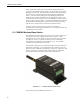
Wireless Sensor Network station synchronizes wireless sensor measurements and polls all sensors, storing the collected measurements so that it can transfer them as soon as the datalogger requests them. This minimizes the amount of time the datalogger needs to wait for a response from the network through the CWB100 base station. At the start of each polling interval the datalogger polls the base station and sensor values are transferred to the datalogger for storage.
Wireless Sensor Network 1.3 CWS220 Wireless Infrared Radiometer The CWS220 is a Wireless Infrared Radiometer that incorporates Apogee Instrument's SI-111 infrared sensor to provide a non-contact means of measuring the surface temperature of an object. It senses the infrared radiation being emitted by the target. The CWS220 is used to measure leaf, canopy, and average surface temperature.
Wireless Sensor Network 1.4 CWS655 Wireless Water Content Reflectometer The CWS655 is based on Campbell Scientific’s CS655 water content reflectometer. It measures volumetric soil water content, electrical conductivity (EC), dielectric permittivity, and ambient temperature of soils or other porous media. The water content information is derived from the probe’s sensitivity to the dielectric permittivity of the medium surrounding its stainless-steel rods.
Wireless Sensor Network The CWS655 outputs 8 values: Volumetric water content, Bulk electrical conductivity, Dielectric permittivity, Soil temperature, Period Average, Voltage ratio, Internal temperature, Battery voltage, and Signal strength. Additional detail regarding CWS655 output is available in Appendix B. For specifications of the CWS655, see Section 2.4. 1.5 CWS900 Wireless Sensor Interface The CWS900 is a Wireless Sensor Interface.
Wireless Sensor Network 6 * * * * * * * * * * * * * * * * * CWS900 Internal Temperature, C * Battery Voltage, V * Signal Strength pH, V Dissolved Oxygen, V Leaf Wetness Sensor, V Relative Humidity Probe Pressure, kPa Probe Temperature, C Avg Pulse Freq during polling interval, Hz Max Pulse Freq during polling interval, Hz Interval Count of Switch Closures Total Count of Switch Closures * * Differential Channel, V * * * Single Ended Channel 3, V Single Ended Channel 2, V Single
Wireless Sensor Network Wind Speed Average, m/s Wind Speed Maximum, m/s Wind Speed Minimum, m/s Wind Speed Std Dev, m/s Wind Dir Avg Unit Vector Mean Wind Dir, deg Wind Dir Std Dev, Yamartino Algorithm, deg Resultant Mean Wind Speed, m/s Resultant Wind Dir Avg, deg Resultant Wind Dir Std Dev CSI algorithm, deg Signal Strength Battery Voltage, V CWS900 Internal Temperature, C Configuration 05103, 05103-45, or 05106 RM Young Wind Monitor 05305 RM Young Wind Monitor 03002 RM Young Wind Sentry Set
Wireless Sensor Network 2. Specifications 2.1 Wireless Sensor Network Radio The CWB100 and CWS sensors use a 25 mW FHSS radio. Three models are available depending on location of usage. Table 2.1-1 shows model numbers and locations used for all models. 2.1.1 Electrical TABLE 2.1-1. CWS FHSS Radio Specifications Model Where Used Frequency FHSS Channels CWSxxx, CWB100 U.S.
Wireless Sensor Network 2.1.2 Typical RF Range RF range is affected by antenna height and by obstacles between the two antennae. The following ranges represent typical distances of RF range as measured with a 0 dBd Omnidirectional 1/2 wave whip antenna connected to the CWB100 radio base station: Base Height Sensor Height RF Range Dense Corn Field 2.1 m (7’) tall 1.2 m (4’) 1.2 m (4’) 0.9 m (3’) 0.0 m (0’) 152 m (500’) 131 m (430’) Inside Industrial Building 1.2 m (4’) 0.
Wireless Sensor Network 2.1.5 Antenna Options All CWS wireless sensors contain a built-in 0 dBd 1/4 wave antenna. No other antenna options are available for the wireless sensors. The CWB100 Wireless Base Station has a RPSMA connector for use with one of several models of antenna. The base station does not automatically ship with an antenna, so one must be ordered as a separate item.
Wireless Sensor Network Terminal Block Connector: Bi-Directional Serial datalogger connection USB Port: Computer connection for configuration Antenna: RPSMA antenna connection Memory: Can store data table for up to 50 wireless sensors. Operating Temperature Range: -25° to +50°C (-13° F to + 122°F) Terminal Block Pin-Out: I/O Name Description In +12V 12V Supply n/a GND Supply Ground i/o DATA/A CPI “A” i/o B CPI “B” n/a ISO_GND CPI Signal Reference 2.2.
Wireless Sensor Network 2.3.2 CWS220 Electrical Specifications Power: 2 AA Batteries Average Current Drain: 300 μA with 15 minute polling Radio: Internal 25 mW FHSS Radio Absolute Accuracy: ±0.2°C @ -10° to +65°C; ±0.5°C @ -40° to +70°C Repeatability: ±0.05°C @ -10° to +65°C; ±0.1°C @ -40° to +70°C Response Time: <1 s to changes in target temperature Wavelength Range: 8 to 14 μm (corresponds to atmospheric window) Field of View (FOV): 22° half angle 2.3.
Wireless Sensor Network 2.4.3 CWS655 Environmental Specifications Temperature Range: -25° to +50°C (-13° F to + 122°F) Humidity Range: 0 to 100% Weather Resistance: IP67 rating for sensor and battery pack (battery pack must be properly installed; each sensor is leak tested) 2.5 CWS900 Specifications 2.5.1 CWS900 Physical Specifications Dimensions: 15 cm x 6 cm x 4.5 cm (6” x 2.4” x 1.8”) Weight: 184 g (6.5 oz) 2.5.
Wireless Sensor Network 2.5.3 CWS900 Environmental Specifications Temperature Range: -25° to +50°C (-13°F to + 122°F) Humidity Range: 0 to 100% Weather Resistance: IP67 rating for sensor and battery back (battery pack must be properly installed; each sensor is leak tested) 3. Getting Started: Creating a Wireless Sensor Network The steps to quickly creating a wireless sensor network are: 1. Obtain the required hardware and software 2. Create a model of the network using default names 3.
Wireless Sensor Network FIGURE 3.1-1. A205 CWS to PC Interface FIGURE 3.1-2. Connection of A205 3.1.2 Required Cables A data cable, CSI part number 17648, ships with the A205. The cable has a USB type A male connector on one end and a type B male connector on the other end. The type B connector is connected directly to the CWB100 without the A205 during configuration and is connected to the A205 when configuring wireless sensors.
Wireless Sensor Network 3.1.3 Configuration CD A Configuration CD ships with each CWB100 Wireless Base Station.
Wireless Sensor Network are specified. As the network is being designed, Wireless Sensor Planner automatically determines many individual device settings. After the model is completed, device settings can be written to the devices using Wireless Sensor Planner. Network Planner version 1.1 or higher, available in LoggerNet 4.1 and higher, can also be used to set up a wireless sensor network. See Section 4 “Setting up Datalogger Networks” in the LoggerNet manual for more information on using Network Planner.
Wireless Sensor Network 3.2.3.1 Simple WSN Example In this example, a CWB100 base station communicates with a CWS655 and a CWS900 with a 109-L-CWS temperature sensor attached. Both sensors are within radio range of the base so no repeaters are necessary. Although station names and measurement names may be customized in Wireless Sensor Planner, the fastest way to configure the network is to use the default names provided.
Wireless Sensor Network Adding Communication Links to Devices The next step is to add links between the base station and the other two devices. This represents the radio communication link between the devices. To create links, click the Link Tool icon on the toolbar. The mouse cursor changes from a hand to a jagged line indicating the Link Tool is currently active. Select CWB100 to indicate that it is the first device in the link. Next drag the resulting line to the CWS655 to complete the link.
Wireless Sensor Network To add the link from the CWB100 to the CWS900, select the CWB100 and drag the resulting line to the CWS900. Another Add Link Between Stations dialog box will appear showing the new link. Click the OK button to accept the link. A new dialog box called Station Link Properties will appear. The CWS900 Wireless Sensor Interface connects to a variety of sensors.
Wireless Sensor Network The Radio ID may be left blank and will be filled in automatically when the device is programmed. Use the Measurement Configuration drop-down list to choose the 109 Temperature Probe. The dialog box also shows the default sensor field names that will be used when a measurement is taken. You can accept the default field names or type in custom field names. After making the selections, press the Apply button to close the dialog box and complete the link. 3.
Wireless Sensor Network shown. To save these settings in a XML file for future reference, click Save and choose a filename. To send these settings to the CWB100, click Connect. After settings have been sent to the CWB100, a new window will show which settings have been applied. This window will provide the option to save the XML file, print it, and compare it to another saved configuration file. After the new settings have been sent to the device, the “Settings have Been Applied” window will appear.
Wireless Sensor Network 3.3.2 Configuring the CWS655 To configure the CWS655 Water Content Reflectometer, first connect the A205 to the type B USB connector on the 17648 cable. Remove the battery door on the CWS655 and locate the four-pin connector near the top of the sensor. Connect the A205 to the sensor at the four-pin connector. The A205 label should be facing toward the CWS655 antenna. Select the Program settings for CWS655_1:CWS655 item in the Configure Devices list, then select Click Here.
Wireless Sensor Network 3.3.3 Configuring the CWS900 To configure the CWS900 Wireless Sensor Interface, first connect the A205 to the type B USB connector on the 17648 cable. Remove the battery door on the CWS900 and locate the four-pin connector near the top of the sensor. Connect the A205 to the sensor at the four-pin connector. The A205 label should be facing toward the CWS900 antenna. Select the Program settings for CWS900_1:CWS900 item in the Configure Devices list, then select Click Here.
Wireless Sensor Network transmitted by wireless sensors. See Section 4.2.1 for more information on the format and use of the configuration string. After the configuration settings have been sent to the base station and wireless sensors, the sensor configuration file may be sent to the datalogger. The datalogger must then be programmed to access that file using the third parameter of the CWB100 instruction. See Section 5 for programming details.
Wireless Sensor Network Determining Size of the Array In this example the WSN includes a CWS655 and a CWS900 configured to measure a 109 temperature probe. Section 1.3 shows that the CWS655 transmits 8 values and Section 1.4 shows that the CWS900 transmits 4 values when configured to measure a 109 probe.
Wireless Sensor Network Finishing the Program Add a one minute data table and CallTable instruction to complete the program Public WSN(12) DataTable (WSNData,True,-1) DataInterval (0,1,Min,0) Sample (12,WSN(),FP2) EndTable BeginProg Scan (60,Sec,0,0) CWB100(1, WSN(),"CPU:CWSConfig.txt") CallTable WSNData NextScan EndProg Save the program and send it to the datalogger.
Wireless Sensor Network Power the CWS sensors by attaching the battery pack to the 4-pin connector. The red LED light will hold steady for about 4 seconds and then turn off. Press and hold the Setup button on the back of the sensor. The blue LED light will flash up to four times indicating the battery voltage then stop flashing. When the Setup button is continually pressed, about four seconds later the blue LED will start flashing again about once per second as the sensor searches for the base station.
Wireless Sensor Network 3.9.2 Connecting Sensors to the CWS900 For sensors that are compatible with the CWS900 but do not have the –LWS connector option available, or for compatible sensors not sold by Campbell Scientific, a connector will need to be added to the sensor in order to interface it with the CWS900. Two options are available. A CWS900 Mating Connector may be purchased from Campbell Scientific and connected to the sensor pigtail.
Wireless Sensor Network TABLE 4.1-1. Values Transmitted by CWS Sensors Sensor Values Transmitted CWS220 Wireless Infrared Radiometer 5 CWS655 Wireless Water Content Reflectometer 8 CWS900 Wireless Sensor Interface* 4 – 10 * See Section 1.4 for more information on number of values transmitted by the CWS900 In the network example shown in Section 3, a CWS655 and a CWS900 configured for a 109-L probe are used. The CWS655 transmits 8 values and the CWS900 transmits 4 values.
Wireless Sensor Network Configuration: The Configuration parameter is an optional constant string parameter that specifies a list of sensor descriptions. This configuration string is supplied by the user to predefine sensor and field names along with the order in which values are returned to the destination array. It overrides the names provided by the sensor and predefines field names. This parameter can specify a file, as in “CPU:CWSConfig.txt”, in which case a file called CWSConfig.
Wireless Sensor Network discovered. This can make it difficult to use specific values in the datalogger program because of uncertainty as to which position in the array the value of interest will be assigned. The CRBasic instruction ArrayIndex may be used to reference values returned by wireless sensors regardless of where those values are in the destination array. See Section 4.3 for details on ArrayIndex. 4.2.
Wireless Sensor Network 4.3 ArrayIndex() Instruction The ArrayIndex function is used to return the index of a named element in an array which would otherwise be unknown. The value can then be further processed in the program because of its known position in the array. If the named element is not found, the function returns 0 (this will result in a Variable Out of Bounds error).
Wireless Sensor Network in the array for program use regardless of the order in which the sensor was discovered. CRBasic instruction Fieldnames is used after each output instruction to provide a unique output name to the values. If more than one output instruction is in the DataTable and Fieldnames is omitted, a compiler error will be returned indicating duplicate output names.
Wireless Sensor Network Port: The Port parameter is a constant indicating the control port (C1, C3, C5, or C7) to which the CWB100 Data line is connected. Routes: A destination variable of type String where the routing information will be stored. It is important to size the variable large enough to hold all of the routing information. Example Public WSNRoutes as String *100 . . .
Wireless Sensor Network Example 4.6-1.
Wireless Sensor Network 5. CWS Button and LED Behavior The Setup button on the back of a CWS sensor and the RED and BLUE LED lights provide diagnostic information regarding the sensor and its communication with the CWB100 base station radio. 5.1 Sensor Link to Base Station Press the Setup button momentarily to see how the CWS sensor is linked to the CWB100 base station.
Wireless Sensor Network 2. If the initial attempt fails to link to the base station, the CWS sensor will delay 5 minutes before attempting to link again. The BLUE LED will be off during this time. The sensor will try to link to the base at a five minute interval a total of three times. 3. If the 5-minute interval attempt fails to link to the base station, the CWS sensor will delay one hour before attempting to link again. The BLUE LED will be off during this time.
Wireless Sensor Network up whenever a measurement is taken and the red LED will light up whenever the measurements are transmitted to the base station. 6. Connect the battery pack to the next wireless sensor, press in the Setup button for 8-10 seconds, and wait for that sensor to pair with the base station radio. It is also possible to power all the sensors at the same time, press the button to start the linking, and wait for them to autodiscover the base station. 7.
Wireless Sensor Network Prior to sensor discovery, the numeric monitor will display the name of the public variable specified in the CWB100 instruction with NAN as the output. Once the sensor has been discovered, NAN will change to Undefined. To view the user-specified Field Names in the numeric monitor, delete the original Public variables from the display with the Delete All button and add the Public table again with the Add button.
Wireless Sensor Network Distilled water or alcohol works well for most dust/dirt. Salt deposits dissolve better in a weak acid solution (~0.1 molar). Sensors connected to the CWS900 may require regular maintenance and recalibration. See the documentation for the sensor of interest for recommended maintenance and recalibration details. 7.
Wireless Sensor Network 8. Troubleshooting Symptom Possible Cause Solution Cannot connect to CWB100 with USB cable Wrong serial port number specified Choose correct serial port number from drop down menu. If correct port number does not display, wait 15 seconds for list to refresh and try again. Device drivers not installed Install device drivers from Configuration CD Cannot connect to CWS sensor with A205 Wrong serial port number specified Choose correct serial port number from drop down menu.
Wireless Sensor Network Symptom Possible Cause Solution Pressing Setup button for 8-10 seconds does not initiate autodiscovery (Blue LED does not blink every second indicating search for base station) Sensor does not have radio base station address programmed into it Reconfigure sensor to include base station radio address First element in destination array specified in CWB100 instruction is -1 and all other elements in the array are zeroes CWB100 is not connected to control port specified in CWB100
Wireless Sensor Network Symptom Possible Cause Solution First element in destination array specified in CWB100 instruction is -3 and all other elements in the array are zeroes. The measurement names in the datalogger do not match the names stored in the CWB100 base station. This is a rare error message that should disappear after the datalogger has made its second attempt to communicate with the CWB100 base station.
Appendix A. Using DevConfig for CWS Setup CWS Sensors can be configured using Device Configuration Utility, DevConfig, which can be downloaded from www.campbellsci.com/downloads. DevConfig does not allow custom field names and will not generate a configuration string, but it can be used to specify the base station radio address, sensor name, and the measurement configuration for the wireless sensor.
Appendix A. Using DevConfig for CWS Setup A-2 5. Once DevConfig connects to the sensor, enter the address of the CWB100 in the field called Base Station Address. If configuring a CWS900, choose the type of measurement the sensor will make from the drop-down menu called Measurement Configuration. If desired, change the Sensor Name from its default value. 6. Click Apply to apply the changes. A configuration summary will be displayed. Save the configuration information if desired. Click OK.
Appendix A. Using DevConfig for CWS Setup 7. If configuring a CWS900 sensor module, you can use DevConfig to ensure that the sensor is correctly configured and connected to the CWS900. To test the sensor, connect the sensor to be measured to the CWS900 and follow the instructions above for establishing communication with DevConfig. When the sensor settings are displayed in the Deployment tab, click on the Settings Editor tab.
Appendix A.
Appendix B. Measurement Names and Meanings Default measurement names are shown in Wireless Sensor Planner, Network Planner, and DevConfig software. Custom names may be assigned to the measurements with Wireless Sensor Planner or Network planner. It is good practice to keep the measurement names short. The default names, meanings and measurement units are listed below. B.
Appendix B. Measurement Names and Meanings B.
Appendix B. Measurement Names and Meanings Default Name Meaning Units BV Battery voltage of wireless sensor Volts Ti Internal temperature of wireless sensor °C WSA Wind speed average during last polling interval meters per second WSMX Wind speed maximum during last polling interval. Calculated from a running average of three successive, one-second wind speed measurements meters per second WSMN Wind speed minimum during last polling interval.
Appendix B. Measurement Names and Meanings Default Name RWDSD Meaning Units Resultant wind direction standard deviation. Vector mean wind direction standard deviation calculated over the polling interval with the CSI wind speed weighted algorithm (See B3.1 for details). Degrees B.3.1 Wind Vector Calculations When a wind speed sample is 0, the CWS900 uses 0 to process scalar or resultant vector wind speed and standard deviation, but the sample is not used in the computation of wind direction.
Appendix B. Measurement Names and Meanings Scalar mean horizontal wind speed, S: S=(Σsi)/N where in the case of orthogonal sensors: Si=(Uei2+Uni2)1/2 Unit vector mean wind direction, Θ1: Θ1=Arctan (Ux/Uy) where Ux=(Σsin Θi)/N Uy=(Σcos Θi)/N or, in the case of orthogonal sensors Ux=(Σ(Uei/Ui))/N Uy=(Σ(Uni/Ui))/N where Ui=(Uei2+Uni2)1/2 Standard deviation of wind direction, σ(Θ1), using Yamartino algorithm: σ(Θ1)=arc sin(ε)[1+0.1547 ε3] where, ε=[1-((Ux)2+(Uy)2)]1/2 and Ux and Uy are as defined above.
Appendix B. Measurement Names and Meanings Standard deviation of wind direction, σ(Θu), using Campbell Scientific algorithm: σ(Θu)=81(1- U /S)1/2 The algorithm for σ(θu) is developed by noting (Figure B.3-3) that Cos (Θ i ') = U i / si ; where Θ i ' = Θi − Θu FIGURE B.3-3. Standard Deviation of Direction The Taylor Series for the Cosine function, truncated after 2 terms is: Cos (Θ i ') ≅ 1 − (Θ i ') 2 / 2 For deviations less than 40 degrees, the error in this approximation is less than 1%.
Appendix B. Measurement Names and Meanings ∑ ((Θ i ') si ') / NS , is 0 if the deviations in speed are not The term, correlated with the deviation in direction. This assumption has been verified in tests on wind data by CSI; the Air Resources Laboratory, NOAA, Idaho Falls, ID; and MERDI, Butte, MT. In these tests, the maximum differences in 2 σ ( Θu ) = ( ∑ ( Θi ') 2 / N )1/2 and σ ( Θu ) = ( 2 (1 − U / S )) 1/2 have never been greater than a few degrees.
Appendix B.
Appendix C. Battery Life C.1 Battery Characteristics The battery life of the CWS wireless sensors is a function of the polling interval, repeater usage, type of batteries, and temperature.
Appendix C. Battery Life Sensor and Connection 5 Min Polling 10 Min Polling 15 Min Polling CWS900 w/109 Probe or CWS655 15 months 21 months 24 months Same as above, used as a repeater for 1 sensor 8 months 12 months 15 months Same as above, used as a repeater for 2 sensors 6 months 8 months 12 months C.3 RF Connection Type Setting In the Device Configuration Utility Settings editor, there is a setting called RF Connection Type.
Appendix C. Battery Life In another situation, there may be a sensor in a location that permits a direct connection to the base, but misses a significant number of data polls. Changing the sensor’s RF Connection Type setting to Connect Through Repeater will force it to go through a repeater, and it will not attempt any direct connection to the base, which may result in fewer missed polls.
Appendix C.
Campbell Scientific Companies Campbell Scientific, Inc. (CSI) 815 West 1800 North Logan, Utah 84321 UNITED STATES www.campbellsci.com • info@campbellsci.com Campbell Scientific Africa Pty. Ltd. (CSAf) PO Box 2450 Somerset West 7129 SOUTH AFRICA www.csafrica.co.za • cleroux@csafrica.co.za Campbell Scientific Australia Pty. Ltd. (CSA) PO Box 444 Thuringowa Central QLD 4812 AUSTRALIA www.campbellsci.com.au • info@campbellsci.com.au Campbell Scientific do Brazil Ltda.