
User Manual


VDIV10.1, VDIV2.1 Voltage Divider Terminal Input Modules
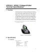
H
L
or G
H
L
G
90 kΩ
10 k
Ω
90 kΩ
10 kΩ
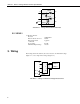
FIGURE 2-1. Voltage Divider Module Schematic
2.2 VDIV2.1
2:1 Resistive Divider
Resistors
10 kΩ/10 kΩ
Ratio Tolerance @ 25 °C
±0.02%
Ratio Temperature
coefficient
2 ppm/°C
Power rating 0.25 W
Maximum Input Voltage 10 volts
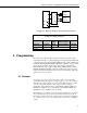
3. Wiring
Each voltage divider module may be used to measure one differential voltage
(Figure 3-1) or two single-ended voltages (Figure 3-2).
Datalogger
H
L
AG or
G or
Shield
SENSOR
H Output
L Output
H
L
G
FIGURE 3-1. Wiring for Differential Voltage Measurement
2