
Owner manual

UT10 Weather Station
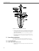
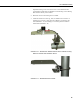
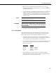
FIGURE 7-6. UT10 Mounting Foot Detail View
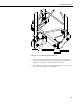
6. Check the UT10 for plumb using a level and adjust the leveling nuts below
the mounting feet on the J-bolts as required. When the tower is plumb, use
two wrenches to lock the lower nuts on each J-bolt together. Tighten the
upper nuts to secure the base.
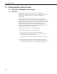
7. Removing the lower 3/8 inch bolt on the rear (West) leg allows the tower
to be hinged to the ground. If a step ladder is available, it is easier to leave
the tower upright.
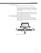
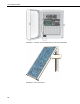
7.2 Sensor Mounting Brackets
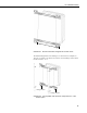
Sensor mounting brackets provide a means of mounting the sensors to the
tower. General orientation of the mounting brackets is shown in FIGURE 7-7.
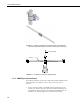
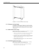
7.2.1 Crossarm Mounting
7.2.1.1 CM202, CM203, CM204, CM206 Crossarms
1. Attach the crossarm at the desired height via the provided U-bolts and nuts
(FIGURE 7-8).
12