TX312 Transmitter Revision: 12/10 C o p y r i g h t © 2 0 0 0 - 2 0 1 0 C a m p b e l l S c i e n t i f i c , I n c .
Warranty and Assistance The TX312 TRANSMITTER is warranted by Campbell Scientific, Inc. to be free from defects in materials and workmanship under normal use and service for twelve (12) months from date of shipment unless specified otherwise. Batteries have no warranty. Campbell Scientific, Inc.'s obligation under this warranty is limited to repairing or replacing (at Campbell Scientific, Inc.'s option) defective products.
TX312 Transmitter Table of Contents PDF viewers note: These page numbers refer to the printed version of this document. Use the Adobe Acrobat® bookmarks tab for links to specific sections. 1. Introduction..................................................................1 2. GOES System...............................................................3 2.1 Orbit..........................................................................................................3 2.2 NESDIS and Transmit−Windows............
TX312 Transmitter Table of Contents 4.5.2.4 GPS Status .......................................................................... 12 4.5.2.5 Read Audit Log................................................................... 13 4.5.2.6 Enable Transmitter.............................................................. 13 4.5.2.7 Disable Transmitter ............................................................ 13 4.5.2.8 Max Timed Message Length .............................................. 13 4.5.2.
TX312 Transmitter Table of Contents 5.2.5.6 P127, Command 5: Clear TX312 Error Registers ..............32 5.2.5.7 P127, Command 6: Return TX312 to on-line mode. ..........32 5.2.6 Edog Programming Examples.......................................................32 6. Field Installation ........................................................35 6.1 Field Site Requirements..........................................................................35 6.2 Transmission Antenna .....................................
TX312 Transmitter Table of Contents Tables 5.1-1. GoesStatus Command 0: Read Time ................................................ 18 5.1-2. GoesStatus Command 1: Read Status............................................... 18 5.1-3. GoesStatus Command 2: Read Last Message Status ........................ 19 5.1-4. GoesStatus Command 4: Read TX312 Error Registers .................... 19 5.1-5. Error Codes........................................................................................ 20 5.1-6.
TX312 Transmitter 1. Introduction The TX312 transmitter supports one-way communication, via satellite, from a Campbell Scientific datalogger to a ground receiving station. Satellite telemetry offers a convenient telecommunication alternative for field stations where phone lines or RF systems are impractical.
TX312 Transmitter Specifications: On-board memory: Transmission Data Rates: Power requirements: 25316 Transmit Antenna: 2 Non-volatile flash for setup parameters. 16 kbytes for data 100, 300 and 1200 bps 10.8 to 16 VDC, 5 mA quiescent, 90 mA during GPS fix and 2.6 Amps during transmission 11 dBi Gain, Right Hand Circular polarization, Type N female connector, wind load of ~100 knots Transmit power: 5.6 watts for 100 and 300 bps, 11.2 watts for 1200 bps Frequency Range: 401.701 MHz to 402.
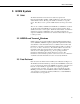
TX312 Transmitter 2. GOES System 2.1 Orbit The TX312 transmitter sends data via Geostationary Operational Environmental Satellites (GOES). GOES satellites have orbits that coincide with the Earth's rotation, allowing each satellite to remain above a specific region. This allows a user to point the GOES antenna at a fixed position in the sky. There are two satellites, GOES East and GOES West. GOES East is located at 75° West longitude and GOES West is located 135° West longitude.
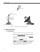
TX312 Transmitter GOES Satellite Satellite Antenna GOES transmitter, datalogger, and power supply, also known as a DCP Ground Receiving Station Data Collection Platform (DCP) FIGURE 2-1. Major Components of the GOES/DCP System 3. TX312 Functions 3.1 LED Function The TX312 has four LEDs used to indicate the state of the TX312 transmitter. When power is first applied to the TX312, the four LEDs will cycle through quickly, then the Synchronizing Clock to GPS LED will light for 15 minutes.
TX312 Transmitter 3.2 Diagnostics Switch The Diagnostics switch has two purposes. Press and hold the Diagnostics button for about 2 seconds. The Fault LED will flash once to indicate the Failsafe has not been tripped. If the LED flashes twice, the Failsafe has tripped. To clear the Failsafe, press and hold the diagnostic button for about 10 seconds. If the failsafe has tripped, the transmitter probably needs to be returned for service.
TX312 Transmitter 3.4 RF Connectors 3.4.1 RF Transmission Connector The TX312 utilizes the type N female connector for RF power out. This connector must have a proper antenna connection before transmission occurs. Failure to use a properly matched antenna cable and antenna may cause permanent damage to the RF amplifiers. The nominal impedance is 50 ohms, the frequency range is approximately 400 to 403 MHz. At 100 and 300 BPS transmission rates, the nominal EIRP is 48 dBm with an 11 dBic gain antenna.
TX312 Transmitter drop, keep the battery power leads short. A five-foot power lead is a long power lead. If you must have a longer lead, use heavy wire. For power leads less than ten feet but more than five feet, use no smaller than 18 AWG. FIGURE 3-1.
TX312 Transmitter FIGURE 3-2. TX312 Connectors FIGURE 3-3.
TX312 Transmitter 4. SatCommand Software Certain information required by NESDIS is unique to each DCP. This setup information includes: platform ID, transmission baud rate, channel number, scheduled transmission time, offset time, and message window length. The TX312 has non-volatile memory to store the setup information. The setup information is entered in the SatCommand software, then transferred to the TX312. SatCommand software is a 32-bit windows application.
TX312 Transmitter you’ve been given a 100/300 channel number. In SatCommad, don’t enter the letter A. When 0 is entered, self-timed transmissions are disabled. 4.3.3 Timed Bit Rate Enter the assigned channel bit rate (baud rate). Valid entries are 100, 300, or 1200. The bit rate is assigned by NESDIS and is tied to the channel number. Using the wrong bit rate will prevent NESDIS from receiving your data. 4.3.4 Timed Interval The Timed Interval is how often data is transmitted.
TX312 Transmitter 4.3.9 Random Bit Rate Enter the assigned channel bit rate (baud rate). Valid entries are 100, 300, or 1200. The bit rate is assigned by NESDIS and is tied to the channel number. Using the wrong bit rate will prevent NESDIS from receiving your data. 4.3.10 Random Randomizing Interval The Randomizing Interval is the average time between random transmissions. When the TX312 receives data in the random data buffer, a random transmission is scheduled.
TX312 Transmitter After the information from Section 4.3 has been entered, select the Save/Send Settings button. Provide a file name to save the settings to disk, then select the Yes button on the Send to Transmitter dialog box. The settings will be transferred to the TX312. Once the transfer is complete, select the Status button to verify the transmitter is setup and enabled. Specifically, look for the line that says Transmitter: Enabled.
TX312 Transmitter 4.5.2.5 Read Audit Log The Read Audit Log will display a history of the transmitter operation. The latest entry in the audit log is shown at the top of the screen. The audit log will record any error condition that has occurred in the past, plus other events. 4.5.2.6 Enable Transmitter The Enable transmitter will enable the transmissions if the transmitter setup parameters are all valid; otherwise, the transmitter cannot be enabled. 4.5.2.
TX312 Transmitter 4.5.2.15 Show Defaults The Show Defaults will populate the edit window with default values, which are not valid for transmission. Selecting show defaults, then sending the defaults to the transmitter will return the transmitter to factory default settings and prevent transmission of data. Once the defaults are loaded to the edit window, the defaults can be edited. Sometimes it is useful to start from a known condition. 5. Programming the Datalogger 5.
TX312 Transmitter number of records to be copied each time GoesData is executed. When copying data, the entire record is copied from the datalogger to the TX312 transmitter. 5.1.1.4 Buffer Control Buffer Control is used to determine which buffer data is copied to, and if the buffer is erased before data is copied to the buffer. Use Zero to append to the self-timed buffer, use 1 to overwrite the self-timed buffer. Use 2 to append to the random buffer, and 3 to overwrite the random buffer. 5.1.1.
TX312 Transmitter NOTE The order data appears in each transmission can be controlled. Only whole records are copied from the datalogger to the TX312. Each record is copied in the same order it appears in the datalogger memory. The order of data records, oldest to newest or newest to oldest, can be controlled. To arrange data records oldest to newest, execute the GoesData instruction when data is written to the data table.
TX312 Transmitter DataTable(GoesStats,true,300) DataInterval(0,1,hr,0) Sample(14,LastStatus(),fp2) EndTable BeginProg Scan (10,Sec,3,0) Battery (battery1) PanelTemp (PanelT,250) TCDiff (TCTemp,1,mV25C ,2,TypeT,PanelT,True ,0,250,1.8,32) CallTable TempData If IfTime (0,1,Hr) GOESData (RC_Data,TempData,0,0,1) EndIf If IfTime (0,10,min) GOESStatus (LastStatus(),2) EndIf CallTable GoesStats NextScan EndProg 5.1.2 GoesStatus The GoesStatus instruction is used to read information from the TX312.
TX312 Transmitter reading the time from the TX312. The array needs to be four elements or more. Data is returned as: Result Code, Hour, Minute, Second. TABLE 5.1-1. GoesStatus Command 0: Read Time Index Contents 1 2 3 4 Command Result Code Hours (GMT) Minutes Seconds 5.1.2.2 GoesStatus Read Status Example: Public Stats(13) GoesStatus(Stats(), 1) Command 1, (Read Status) is used to read information regarding the current status of the transmitter.
TX312 Transmitter TABLE 5.1-3.
TX312 Transmitter TABLE 5.1-5.
TX312 Transmitter Error code 18 (0x12), message abort due to power supply, indicates the transmitter power supply did not provide enough voltage. Check system battery. If the system battery is low, the RF power supply will not be able to operate properly. The loaded battery voltage must not drop below 10.8 volts. Error code 19 (0x13), Software error, indicates the transmitter was not able to run its internal software. Error code 20 (0x14) is the Failsafe error.
TX312 Transmitter includes the result code (see Table 5.1-6), time in seconds since January 1, 2000, Latitude in fractional degrees with 100 nanodegree resolution, Longitude in fractional degrees with 100 nanodegree resolution, Elevation as a signed 32bit number in centimeters, and Magnetic Variation in fractional degrees with a one millidegree resolution. The second array, which must be dimensioned to seven, holds year, month, day, hour (GMT), minute, seconds, microseconds.
TX312 Transmitter 5.1.4.1 Result Code Result Code is used to indicate success or failure. Zero indicates Success. Positive result codes indicate communication problems; negative result codes indicate an illegal value in one of the parameters. See Table 5.1-6 for positive result codes and Table 5.1-7 for negative result codes. TABLE 5.1-6.
TX312 Transmitter 5.1.4.6 Random Channel Random channel is the assigned random channel number. See Timed Channel description for valid entries. 5.1.4.7 Random Baud Rate Random Baud rate is assigned and channel dependent. Valid options are 100, 300, and 1200. 5.1.4.8 Timed Interval Timed Interval is assigned by NESDIS and is a string variable in the format of “dd_hh_mm_ss”, where dd is days and usually 00, hh is hours and usually 01, mm is minutes and usually 00, and ss is seconds and usually 00. 5.1.4.
TX312 Transmitter of repetitions has been met. When properly configured, the TX312 will ensure the data is transmitted on the correct channel, at the correct baud rate and at the correct time without overrunning the transmit window. The datalogger will interface with the TX312 under program control. Two program instructions are used, P126 and P127. P126 is used to send data to a buffer. New data is either added to existing data (append) or overwrites existing data.
TX312 Transmitter datalogger formats the data before the data is sent to the TX312. The data format is chosen with the P126 program instruction. 5.2.3 Managing Data, Writing More Data than Will Be Transmitted The datalogger has two data storage areas: Final Storage area 1 (FS1) and Final Storage area 2 (FS2). When data is written to final storage, data is written to the active final storage area. The active final storage area defaults to FS1 when the datalogger starts the program table.
TX312 Transmitter 5.2.4.1 Buffer Control The first parameter of Edlog instruction 126 (P126) is called buffer control. Buffer control has two purposes: 1) to determine which buffer data is written to, and 2) if the buffer is erased before data is written. The TX312 has two independent buffers, one for self-timed transmissions and one for random transmissions. The self-timed buffer is treated differently than the random buffer. After a self-timed transmission, the data is erased from the self-timed buffer.
TX312 Transmitter 3) The command to select a data buffer is sent (random or self-timed). The transmitter should respond with the ACK (06) character. If something besides the ACK is received, result code is 4. If nothing is received within 500 msec, result code is 5. 4) If the first three steps are successful, the datalogger sends the command to append or overwrite the data buffer, followed by the data.
TX312 Transmitter Parameter 2 is the starting input location for the string of information the TX312 will return. Each P127 command returns a string of information. Each command requires a different number of input locations. The first piece of information returned is always the result code of the command. Table 5.2-1 lists the result codes and explains them. TABLE 5.2-1.
TX312 Transmitter TABLE 5.2-3.
TX312 Transmitter TABLE 5.2-5. P127 Command 3: Initiate Random Transmission In Loc Contents 1 Result Code Random message channel and repeat interval must be enabled in the TX312 configuration. If random messages have not been enabled, command 3 will fail. If the GPS acquisition fails, the random transmission will fail. Command 3 will pull the TX312 off line. After the random transmission attempt, the TX312 must be put back on line with command 6. When command 6 is used, all data in the TX312 is erased.
TX312 Transmitter TABLE 5.2-7.
TX312 Transmitter Edlog program example 1 writes data to final storage once an hour and transfers data to the TX312 once every 4 hours.
TX312 Transmitter ; Write a time stamp to final storage 2: Real Time (P77) 1: 1221 Year,Day,Hour/Minute,Seconds (midnight = 2400) ; Write 41 input locations to final storage 3: Sample (P70) 1: 41 2: 1 Reps Loc [ Status_RC ] ; Check if top of 4 hour interval, if true execute P126 4: If time is (P92) 1: 0 Minutes (Seconds --) into a 2: 240 Interval (same units as above) 3: 30 Then Do ; Transfer data to TX312 5: Data Transfer to HDR GOES (P126) 1: 0 Self-Timed/Append 2: 0 Binary Format 3: 41 Result Code Loc
TX312 Transmitter ; Check number of times P126 has been executed unsuccessfully ; If P126 failed more than 3 times, give up and reset counter 11: If (X<=>F) (P89) 1: 42 X Loc [ Counter ] 2: 3 >= 3: 4 F 4: 30 Then Do ; Reset counter 12: Z=F (P30) 1: 0.0 2: 00 3: 42 F Exponent of 10 Z Loc [ Counter ] ; Set P126 result code to zero, this will stop P126 from ; executing until the 4 hour transmit time comes around again. 13: Z=F (P30) 1: 0.
TX312 Transmitter received power will be half of a properly aimed antenna. Beyond 25 degrees, the received power drops off very quickly. 6.3 GPS Antenna 6.3.1 How the GPS Signal is Acquired and Used The GPS receiver will acquire a complete GPS fix at power up and once a day. The TX312 transmitter will continue to operate normally for 28 days without a GPS fix. The GPS signal is used for two functions. The obvious use is to keep track of time. The GPS receiver requires 3 satellites to acquire the time.
Appendix A. Information on Eligibility and Getting Onto the GOES System A.1 Eligibility U.S. federal, state, or local government agencies, or users sponsored by one of those agencies, may use GOES. Potential GOES users must receive formal permission from NESDIS. A.2 Acquiring Permission 1. The user contacts NESDIS at the following address and submits a formal request to transmit data via GOES. Non-U.S.
This is a blank page.
Appendix B.
This is a blank page.
Appendix C. Antenna Orientation Computer Program (written in BASIC) 5 6 10 20 30 40 45 50 60 70 80 90 100 110 115 120 130 140 150 155 160 170 180 190 200 210 220 300 310 320 330 340 350 360 370 380 400 460 REM THIS PROGRAM CALCULATES THE AZIMUTH AND ELEVATION FOR AN REM ANTENNA USED WITH A DCP FOR GOES SATELLITE COMMUNICATIONS CLS : CLEAR 1000 INPUT "SATELLITE LONGITUDE (DDD.DD)"; SO INPUT "ANTENNA LONGITUDE (DDD.DD)"; SA PRINT "ANTENNA LATITUDE (DDD.
This is a blank page.
Appendix D. RAWS-7 Data Format D.1 Introduction RAWS-7 data format is used to transmit weather data in an ASCII based table format. Upon reception, data does not need to be decoded. Software such as WeatherPro can be used to archive and view the data. RAWS-7 data format is compatible with NIFC. D.2 Format RAWS-7 format writes data in columnar format. The first 7 data points are written to column 1, the next 7 data points are written to column 2 and the next 7 data points are written to column 3.
Appendix D. RAWS-7 Data Format D.4 RAWS-7 Sample Data 00.12 00.05 01.09 109 022 002 234 123 087 115 069 -23 100 056 012 056 098 012 10.5 11.9 13.6 Rain fall: Hundredths of and inch Wind Speed: Avg of last 10 minutes Wind Direction: Avg of last 10 minutes Air Temperature: Sample Relative Humidity: Avg of Last 10 minutes Fuel Temperature: Sample Battery Voltage: Sample Oldest data in left column Table D-1. RAWS-7 Output Row Number Measurement Format 1 2 3 4 5 6 7 Total Rain (hr) Wind Speed (10 min avg.
Appendix D. RAWS-7 Data Format P126 format code 3 ASCII RAWS-7 format, 1, 2 or 3 columns 1 2 3 4 5 6 7 Total Rain Avg Wind Speed Avg Wing Direction Sample Air Temp Avg Relative Humidity Sample Fuel Temp Battery Voltage xx.xx xxx xxx xxx xxx xxx xx.x P126 format code 4 ASCII fixed decimal xxx.x P126 format code 5 ASCII fixed decimal xx.xx P126 format code 6 ASCII fixed decimal x.xxx P126 format code 7 ASCII fixed decimal xxx P126 format code 8 ASCII fixed decimal xxxxx D.
Appendix D.
Appendix D. RAWS-7 Data Format ; Measure Fuel Moisture ; Wiring: ; Power enable: C8 ; Signal: SE 12 4: Period Average (SE) (P27) 1: 1 Reps 2: 4 200 kHz Max Freq @ 2 V Peak to Peak, Period Output 3: 12 SE Channel 4: 10 No. of Cycles 5: 5 Timeout (units = 0.01 seconds) 6: 28 Loc [ FuelM ] 7: .001 Mult 8: 0 Offset 5: Do (P86) 1: 58 Set Port 8 Low ; Measure temperature and RH (HMP45C-L) 6: Excitation with Delay (P22) 1: 1 Ex Channel 2: 0 Delay W/Ex (units = 0.01 sec) 3: 15 Delay After Ex (units = 0.
Appendix D. RAWS-7 Data Format ; Wind Direction (03001-L) 10: Excite-Delay (SE) (P4) 1: 1 Reps 2: 5 2500 mV Slow Range 3: 3 SE Channel 4: 2 Excite all reps w/Exchan 2 5: 2 Delay (units 0.01 sec) 6: 2500 mV Excitation 7: 6 Loc [ Wdir ] 8: 0.142 Mult 9: 0 Offset ; Measure fuel temp 11: Temp (107) (P11) 1: 1 Reps 2: 9 SE Channel 3: 3 Excite all reps w/E3 4: 7 Loc [ FuelT ] 5: 1.
Appendix D. RAWS-7 Data Format 16: End (P95) ; Correct Fuel Moisture 17: Polynomial (P55) 1: 1 Reps 2: 28 X Loc [ FuelM ] 3: 28 F(X) Loc [ FuelM ] 4: -220.14 C0 5: 365.89 C1 6: -114.96 C2 7: 0.0 C3 8: 0.0 C4 9: 0.0 C5 ; Convert Air Temp to degrees F 18: Z=X*F (P37) 1: 3 X Loc [ AirTemp ] 2: 1.8 F 3: 3 Z Loc [ AirTemp ] 19: Z=X+F (P34) 1: 3 X Loc [ AirTemp ] 2: 32.
Appendix D.
Appendix D.
Appendix D. RAWS-7 Data Format 45: Sample (P70) 1: 1 Reps 2: 10 Loc [ Avg10WS ] 46: Sample (P70) 1: 1 Reps 2: 11 Loc [ Avg10WD ] 47: Sample (P70) 1: 1 Reps 2: 3 Loc [ AirTemp ] 48: Sample (P70) 1: 1 Reps 2: 7 Loc [ FuelT ] 49: Sample (P70) 1: 1 Reps 2: 4 Loc [ RH ] 50: Minimum (P74) 1: 1 Reps 2: 0 Value Only 3: 1 Loc [ BattVolt ] ; Send the basic RAWS-7 data to the SAT HDR GOES 5 minutes before transmit time. ; FS 1 must contain only the new RAWS-7 data, 3 hours of data.
Appendix D. RAWS-7 Data Format ; FIRST HOUR ; First hour (column 1) is the top of the first hour after ; the transmit window.
Appendix D. RAWS-7 Data Format ;SECOND HOUR ; At the second hour of a 3 hour interval, move hourly data ; values to the "mid" place holders.
Appendix D.
Appendix D. RAWS-7 Data Format ; xxx xxx xxx ; xxx xxx xxx ; xxxxx xxxxx xxxxx ; xxx xxx xxx Dir Max WS : Max WS : Avg SRad : fuel mois : Oldest to the left Oldest to the left Oldest to the left Oldest to the left ;P126 Instruction, Parameter 2 Options ; 3 RAWS-7 Output ; 4 xxx.x ASCII Output ; 5 xx.xx ASCII Output ; 6 x.
Appendix D.
Appendix D. RAWS-7 Data Format 3: Z=X*F (P37) 1: 35 2: .
Appendix D.
Appendix D. RAWS-7 Data Format This is a blank page.
Appendix E. GOES DCS Transmit Frequencies 300 & 100 BPS Channels Channel Frequency Number MHz 1 2 3 4 5 6 7 8 9 10 11 12 13 14 15 16 17 18 19 20 21 22 23 24 25 26 27 28 29 30 31 32 33 34 35 36 37 38 39 40 41 42 43 44 45 46 47 401.701000 401.702500 401.704000 401.705500 401.707000 401.708500 401.710000 401.711500 401.713000 401.714500 401.716000 401.717500 401.719000 401.720500 401.722000 401.723500 401.725000 401.726500 401.728000 401.729500 401.731000 401.732500 401.734000 401.735500 401.737000 401.
Appendix E. GOES DCS Transmit Frequencies 300 & 100 BPS Channels Channel Frequency Number MHz 95 96 97 98 99 100 101 102 103 104 105 106 107 108 109 110 111 112 113 114 115 116 117 118 119 120 121 122 123 124 125 126 127 128 129 130 131 132 133 134 135 136 137 138 139 140 141 142 143 144 E-2 401.842000 401.843500 401.845000 401.846500 401.848000 401.849500 401.851000 401.852500 401.854000 401.855500 401.857000 401.858500 401.860000 401.861500 401.863000 401.864500 401.866000 401.867500 401.869000 401.
Appendix E. GOES DCS Transmit Frequencies 300 & 100 BPS Channels Channel Frequency Number MHz 195 196 197 198 199 200 201 202 203 204 205 206 207 208 209 210 211 212 213 214 215 216 217 218 219 220 221 222 223 224 225 226 227 228 229 230 231 232 233 234 235 236 237 238 239 240 241 242 243 244 401.992000 401.993500 401.995000 401.996500 401.998000 401.999500 402.001000 402.002500 402.004000 402.005500 402.007000 402.008500 402.010000 402.011500 402.013000 402.014500 402.016000 402.017500 402.019000 402.
Appendix E. GOES DCS Transmit Frequencies This is a blank page.
Appendix F. High Resolution 18-Bit Binary Format When using the binary 18 bit signed 2’s complement integer format, all data values in the datalogger final storage area must be in high resolution format. In most cases the datalogger program should set the data resolution to high at the beginning of the program. Use the P78 instruction with parameter 1 set to 1. Note: P77 Real Time can not write the time or date in high resolution.
Appendix F. High Resolution 18-Bit Binary Format Where 17 represents bit 17 - the most significant bit and is used to determine the sign. Converting the 18 bit data point to an integer can be done manually. Don’t forget the 18 bits are numbered 0 through 17. Bit 17 is the sign bit, when bit 17 is set, the number is negative. If bit 17 is set, subtract 1 from the number then take the complement of the number. If bit 17 is not set, simply convert the number to its decimal equivalent.
Appendix G. Extended ASCII Command Set Appendix G describes the ASCII command interface for the TX312 transmitter. These commands can be entered using the terminal window of SatCommander software, or suitable terminal emulation software. G.1 Command Interface G.1.1 RS-232 Serial Port Interface All Data Entry and Diagnostic functions are accessed using the RS-232 Interface. G.1.1.1 RS232 Hardware Interface The default settings for the RS-232 port are 9600 baud, 8 data bits, no parity and 1 stop bit.
Appendix G.
Appendix G. Extended ASCII Command Set G.2.2 Replacement Character Read/Set Syntax: IRC=c Access level: USER TX312 State: Enabled/Disabled This command defines the ASCII character that will be substituted for any Prohibited ASCII character detected in the transmission data when operating in ASCII or Pseudo-Binary mode. The default character is ‘*’. Only printable ASCII characters, excluding space, are permitted. In Pseudo-Binary mode, numeric characters are considered illegal. G.2.
Appendix G. Extended ASCII Command Set G.2.6 Enable Transmissions Syntax: ETX Access level: USER TX312 State: Disabled This command enables transmissions. The configuration parameters will be checked for validity. If valid, they are saved to non-volatile memory and the transmitter is enabled. The enabled/disabled state of the transmitter is also stored in non-volatile memory so that it will resume operation after a power cycle if it was previously enabled.
Appendix G. Extended ASCII Command Set G.2.9 Enable Technician Command Mode Syntax: TECHMODE password Access level: USER TX312 State: Enabled/Disabled This command changes the command access level to TECHNICIAN. The access level will not change unless the password is correct. G.2.10 Enable User Command Mode Syntax: USERMODE Access level: USER TX312 State: Enabled/Disabled This command changes the command access level back to USER. No password is required.
Appendix G. Extended ASCII Command Set G.3.1 Set GOES DCP Platform ID Syntax: NESID=xxxxxxxx Access level: USER TX312 State: Disabled Sets the transmitter’s GOES DCP Platform ID to the hex value xxxxxxxx. Valid range is even hex numbers from 2 to 0xfffffffe. G.3.2 Set Self-Timed Transmission Channel Number Syntax: TCH=ccc Access level: USER TX312 State: Disabled This command sets the channel number (ccc) for timed transmissions.
Appendix G. Extended ASCII Command Set G.3.5 Set Self-Timed transmission First Transmission Time Syntax: FTT=hh:mm:ss Access level: USER TX312 State: Disabled Set the time for the first timed transmission of the day. Valid range is 00:00:00 to 23:59:59. The First Transmission Time is also referred to as the Offset, and is between 00:00:00 and the Self-Timed Transmission Interval. G.3.
Appendix G. Extended ASCII Command Set G.3.9 Set Self-timed Transmission Preamble Length Syntax: TPR=S/L Access level: USER TX312 State: Disabled Set the preamble type for timed transmissions. Valid values are S or L (Short or Long). This setting only applies for 100 BPS timed transmissions on channels 1-200. All 300 and 1200 BPS transmissions us short preamble. All 100 BPS transmissions on channels above 200 use long preamble. G.3.
Appendix G. Extended ASCII Command Set For 100 BPS operation on channels 201-266, the transmitter will be configured for International operation. Specifically, the 31-bit International EOT will be used (0x63CADD04) in place of the ASCII EOT. Setting the channel number to 0 will disable random transmissions. G.3.
Appendix G. Extended ASCII Command Set The random transmission repeat count is the number of times a random transmission will be repeated. The random transmissions will occur once every random transmission interval as specified by the randomizing interval. The valid range of this parameter is 0 – 99. For example, a value of 3 will direct the transmitter to send the data in the Random buffer 3 times before clearing it.
Appendix G. Extended ASCII Command Set G.4.
Appendix G. Extended ASCII Command Set This command clears the SDI command table entry indicated by i or all SDI-12 commands if i is not specified. G.4.5 Print SDI-12 Commands Syntax: PSDI [i] Where: i is an optional table index indicating the table entry to print. Access level: USER TX312 State: Enabled/Disabled This command prints the SDI command table entry indicated by i or all SDI-12 commands if i is not specified.
Appendix G. Extended ASCII Command Set 2,+348.5,-23.97,-55.7[CR][LF] 1,+3.24,-2.789,///,///[CR][LF] 5,-46,+86,+23.4[CR][LF] 2,+344.5,-28.88,-77.7[CR][LF] 1,+3.55,-2.733,///,///[CR][LF] 5,-24,+86,+25.4[CR][LF] 2,+645.5,-24.88,-77.7[CR][LF] If FC=1 the format is the same except that each record is preceeded by a 24 hour time stamp with the format hh:mm:ss. The time stamp is always in 24 hour form and referenced to UTC.
Appendix G. Extended ASCII Command Set G.4.9 Test SDI-12 Command Table Syntax: STT Access level: USER TX312 State: Enabled/Disabled This command forces the command table to be executed immediately. The measurement results are printed to the terminal rather than being buffered for transmission. G.5 Data Buffer Loading Commands The following commands are used to manage and store data in the GOES Transmission buffers. G.5.
Appendix G. Extended ASCII Command Set G.5.2 Read Number of Bytes in the Self-Timed Transmission Buffer Syntax: TML Access level: USER TX312 State: Enabled/Disabled Returns the number of bytes stored in the timed transmission buffer. G.5.3 Read the Maximum Self-Timed Message Length Syntax: MTML Access level: USER TX312 State: Enabled Returns the maximum number of bytes that can be transmitted with the current timed transmission bit rate, window length and preamble type. G.5.
Appendix G. Extended ASCII Command Set by the random repeat count. The buffer will be cleared automatically when the number of transmissions specified have occurred. If the command is received within 1 minute or during a random transmission the data will not be included in the current transmission but will be buffered for the next one. If there is more data loaded into the buffer than can be transmitted at the assigned bitrate the message will be truncated. G.5.
Appendix G. Extended ASCII Command Set G.6.1 Read Version Information Syntax: VER Access level: USER TX312 State: Enabled/Disabled This command returns the transmitter serial number, hardware version number, firmware version number and GPS module version numbers. G.6.
Appendix G. Extended ASCII Command Set If a transmission has occurred since the unit was last powered up, the transmitter responds to the command with: Tx Status: Failsafe Tripped/OK Tx Type: Timed/Random/Test Last Tx Length: 30 bytes Last Tx Start Time: 2004/12/16 23:29:48 Last Tx Stop Time: 2004/12/16 23:29:49 Forward Power: -23.1 dBm Power Supply: 12.0 V If a transmission has not occurred since power up, the transmitter will respond with: No Tx Has Occurred G.6.
Appendix G. Extended ASCII Command Set G.6.5 Read GPS Position Syntax: POS Access level: USER TX312 State: Enabled/Disabled This command returns position obtained during the last GPS fix in the following format: Time of fix: dd/mm/yyyy hh:mm:ss[CR][LF] Lat: sxx.xxxxx[CR][LF] Long: sxxx.xxxxx[CR][LF] Alt: xxxxx[CR][LF]> Where latitude is in degrees, + for N and - for S, longitude is in degrees, + for E and – for W and altitude is in meters.
Appendix G. Extended ASCII Command Set G.6.9 Read Reflected Power Syntax: RRFL Access level: USER TX312 State: Enabled/Disabled Returns the reflected power in dBm. This value is updated at the bit rate when transmitting and every 30 seconds when not transmitting. G.6.10 Read Power Supply Syntax: RPS Access level: USER TX312 State: Enabled/Disabled Returns the power supply voltage in Volts. This value is updated at the bit rate when transmitting and every 30 seconds when not transmitting. G.6.
Appendix H.
Campbell Scientific Companies Campbell Scientific, Inc. (CSI) 815 West 1800 North Logan, Utah 84321 UNITED STATES www.campbellsci.com • info@campbellsci.com Campbell Scientific Africa Pty. Ltd. (CSAf) PO Box 2450 Somerset West 7129 SOUTH AFRICA www.csafrica.co.za • cleroux@csafrica.co.za Campbell Scientific Australia Pty. Ltd. (CSA) PO Box 444 Thuringowa Central QLD 4812 AUSTRALIA www.campbellsci.com.au • info@campbellsci.com.au Campbell Scientific do Brazil Ltda.