TB4 and TB4MM Rain Gage Revision: 10/10 C o p y r i g h t © 1 9 9 5 - 2 0 1 0 C a m p b e l l S c i e n t i f i c , I n c .
Warranty and Assistance The TB4 AND TB4MM RAIN GAGES are warranted by Campbell Scientific, Inc. to be free from defects in materials and workmanship under normal use and service for twelve (12) months from date of shipment unless specified otherwise. Batteries have no warranty. Campbell Scientific, Inc.'s obligation under this warranty is limited to repairing or replacing (at Campbell Scientific, Inc.'s option) defective products.
TB4 and TB4MM Table of Contents PDF viewers note: These page numbers refer to the printed version of this document. Use the Adobe Acrobat® bookmarks tab for links to specific sections. 1. General Description.....................................................1 2. Specifications ..............................................................1 3. Installation....................................................................2 3.1 Siting........................................................................
TB4 and TB4MM Table of Contents Tables 4-1. Wiring for Pulse Channel Input.............................................................. 4 4-2. Wiring for Control Port Input................................................................. 5 5-1. Multipliers ..............................................................................................
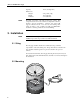
TB4 and TB4MM Rain Gage 1. General Description The TB4 and TB4MM tipping bucket rain gages are manufactured by Hydrological Services Pty. Ltd. (Model TB4) and modified for use with Campbell Scientific dataloggers. These rain gages catch rainfall in the 7.87” (200 mm) diameter collection funnel. When a full bucket of rainfall is collected, the tipping bucket assembly tips and activates a reed switch. The switch closure is recorded by the datalogger pulse channel.
TB4 and TB4MM Rain Gage NOTE Capacity: 12 VA (0.5 amp max.) Dimensions: Weight: Height: Diameter: 4.41 pounds (2 kg) 13 in (330 mm) 7.9 in (200 mm) The black outer jacket of the cable is Santoprene® rubber. This compound was chosen for its resistance to temperature extremes, moisture, and UV degradation. However, this jacket will support combustion in air. It is rated as slow burning when tested according to U.L. 94 H.B. and will pass FMVSS302. Local fire codes may preclude its use inside buildings.
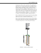
TB4 and TB4MM Rain Gage The rain gage is designed to mount on a flat surface. Three equally spaced mounting pads are provided. The mounting pads are pre-drilled for three 3/8” (M8) bolts on a 9.21” (234 mm) diameter bolt circle. The CM240 mounting bracket is available from Campbell Scientific for installing the TB4. The CM240 base helps level the rain gage, ensuring a more accurate measurement. The base may be attached to a CM300-Series Mounting Pole or to a usersupplied 1.5 IPS (1.9” OD, unthreaded) pipe.
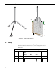
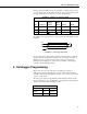
TB4 and TB4MM Rain Gage 3.5” 1.5” 24” 14” FIGURE 3-2. Pedestal Base Options 4. Wiring Connections to Campbell Scientific dataloggers are given in Table 4-1. When Short Cut for Windows software is used to create the datalogger program, the sensor should be wired to the channels shown on the wiring diagram created by Short Cut. TABLE 4-1.
TB4 and TB4MM Rain Gage Dataloggers listed in Table 4-2 have the capability of counting switch closures on some of their control ports. When a control port is used, the return from the rain gage switch must be connected to +5 volts on the datalogger. TABLE 4-2.
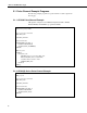
TB4 and TB4MM Rain Gage 5.1 Pulse Channel Example Programs The following example programs use a pulse channel to read the output from the rain gage. 5.1.1 CR1000 Pulse Channel Example Although this example is for the CR1000, Campbell Scientific’s CR800, CR850, CR3000, and CR5000 are programmed similarly.
TB4 and TB4MM Rain Gage 'Main Program BeginProg Scan(10,Sec) 'TB4 Rain Gauge measurement Rain_mm: PulseCount(Rain_mm,P_SW,2,0,0.254,0) 'Call Data Tables and Store Data CallTable(TB4_mm) NextScan EndProg 5.1.
TB4 and TB4MM Rain Gage Output Instruction 72, Totalize, is used in the output section of the program to output the total rainfall over the output interval. This section should be executed every scan and not placed in a subroutine or conditional statement. 5.2 Control Port Example Programs The following examples measure a TB4 rain gage using a control port on the datalogger. Wire the sensor as shown in Table 4-2. 5.2.
TB4 and TB4MM Rain Gage 'Main Program BeginProg Scan (1,Sec) 'TB4 Rain Gage measurement Rain-mm PulseCount (Rain_mm,C2,2,0,.254,0) 'Call Data Tables and Store Data CallTable (Rain) NextScan EndProg ; Black wire connected to C2 5.2.3 CR10X Control Port Example Although this program is for the CR10X datalogger, our CR500, CR510, and CR23X are programmed similarly. ;{CR10X} *Table 1 Program 01: 1.0000 Execution Interval (seconds) 1: Pulse (P3) 1: 1 2: 8 3: 2 4: 1 5: .
TB4 and TB4MM Rain Gage 6. Troubleshooting 6.1 Precipitation Symptom: No Precipitation 1. Check that the sensor is wired to the Pulse Channel specified by the pulse count instruction. 2. Verify that the Configuration Code (Switch Closure), and Multiplier and Offset parameters for the Pulse Count instruction are correct for the datalogger type. 3. Disconnect the sensor from the datalogger and use an ohm meter to do a continuity check of the switch.
TB4 and TB4MM Rain Gage To access the above components, dismantle the TB4 using the following procedure: 1. Remove the housing assembly from the base by loosening the three locking screws and lifting the housing upward. Reed Switch Assembly Bucket Assembly Bullseye Level Housing Screw FIGURE 7-1.
TB4 and TB4MM Rain Gage 2. CAUTION Separate the filter/siphon assembly from the funnel by pushing the filter while pulling the siphon (see Figure 7-2). Do not twist the filter/siphon assembly while pushing and pulling. To dismantle the filter and siphon assembly, push filter and pull siphon at the same time. Do not twist. Push Filter Do not twist while pushing and pulling. Pull Siphon FIGURE 7-2.
TB4 and TB4MM Rain Gage 3. Disassemble the filter/siphon assembly by doing the following (see Figure 7-3): (a) Unscrew nut (b) Lightly press stem down on surface until stem pops out of siphon body. (c) Remove stem from siphon body. (d) Unscrew cap (e) Clean all items Filter Cover Filter Screen Stem Cap Stem O Ring Siphon Body Brass Nut FIGURE 7-3.
TB4 and TB4MM Rain Gage 7.2 Reassembling the TB4 CAUTION 1. Screw cap on stem, finger tighten only (see Figure 7-2). 2. Push stem into siphon body (see Figure 7-2). 3. Replace nut and tighten (see Figure 7-2). Do not over tighten. 4. CAUTION Push filter/siphon assembly back into place (see Figure 7-4). Do not twist the filter/siphon assembly while putting it back into place. To re-assemble, push the filter/siphon assembly back in place. Do not twist. FIGURE 7-4. Reassembling the TB4 5.
TB4 and TB4MM Rain Gage 8. Calibration The sensor is factory calibrated; recalibration is not required unless damage has occurred or the adjustment screws have loosened. Nevertheless, the following calibration check is recommended once every 12 months: Field Calibration Check: a. Remove the housing assembly from the base by removing the three screws and lifting upward on the housing. b. Check the bubble level to verify the rain gage is level. c.
TB4 and TB4MM Rain Gage 16
Campbell Scientific Companies Campbell Scientific, Inc. (CSI) 815 West 1800 North Logan, Utah 84321 UNITED STATES www.campbellsci.com • info@campbellsci.com Campbell Scientific Africa Pty. Ltd. (CSAf) PO Box 2450 Somerset West 7129 SOUTH AFRICA www.csafrica.co.za • cleroux@csafrica.co.za Campbell Scientific Australia Pty. Ltd. (CSA) PO Box 444 Thuringowa Central QLD 4812 AUSTRALIA www.campbellsci.com.au • info@campbellsci.com.au Campbell Scientific do Brazil Ltda.