
Owner's manual
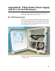
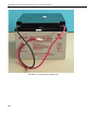


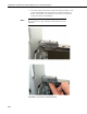
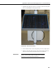
Table Of Contents
- Revision and Copyright Information
- Limited Warranty
- Assistance
- Table of Contents
- 1. Preparation and Siting
- 2. Hardware Installation
- 2.1 Base Foundation
- 2.2 Tower/Pole
- 2.3 Enclosure
- 2.4 Crossarm and Sensor Installation
- 2.5 Communication Peripherals
- 2.6 Lightning Rod Installation
- 2.7 Solar Panel Installation
- 2.8 Battery Installation
- 2.9 Restraining Cables and Sealing/Desiccating Enclosure
- 3. ET Software
- 4. Maintenance, Troubleshooting, and Schematics
- 4.1 Maintenance
- 4.2 Troubleshooting
- 4.2.1 No Response Using the CR1000KD Keypad
- 4.2.2 No Response from Datalogger through SC32B, RAD Modem, or Phone Modem
- 4.2.3 NAN or (INF Displayed in a Variable
- 4.2.4 Unreasonable Results Displayed in a Variable
- 4.2.5 NAN or (INF Stored in a Data Table
- 4.2.6 Communication Problems when using an RF450 Radio
- 4.2.7 Gill WindSonic1-ET Diagnostic Diagnostic Codes
- 4.3 Schematics of Connectors
- Appendix A. T107 Maintenance Log
- Appendix B. PS24 24 Ahr Power Supply and 10 x 12 inch Enclosure
- Appendix C. Exploded Views
- Appendix D. Default Programs
- Appendix E. Step-down Transformer Installation
- Campbell Scientific Companies
Appendix B. PS24 24 Ahr Power Supply and 10 x 12 inch Enclosure
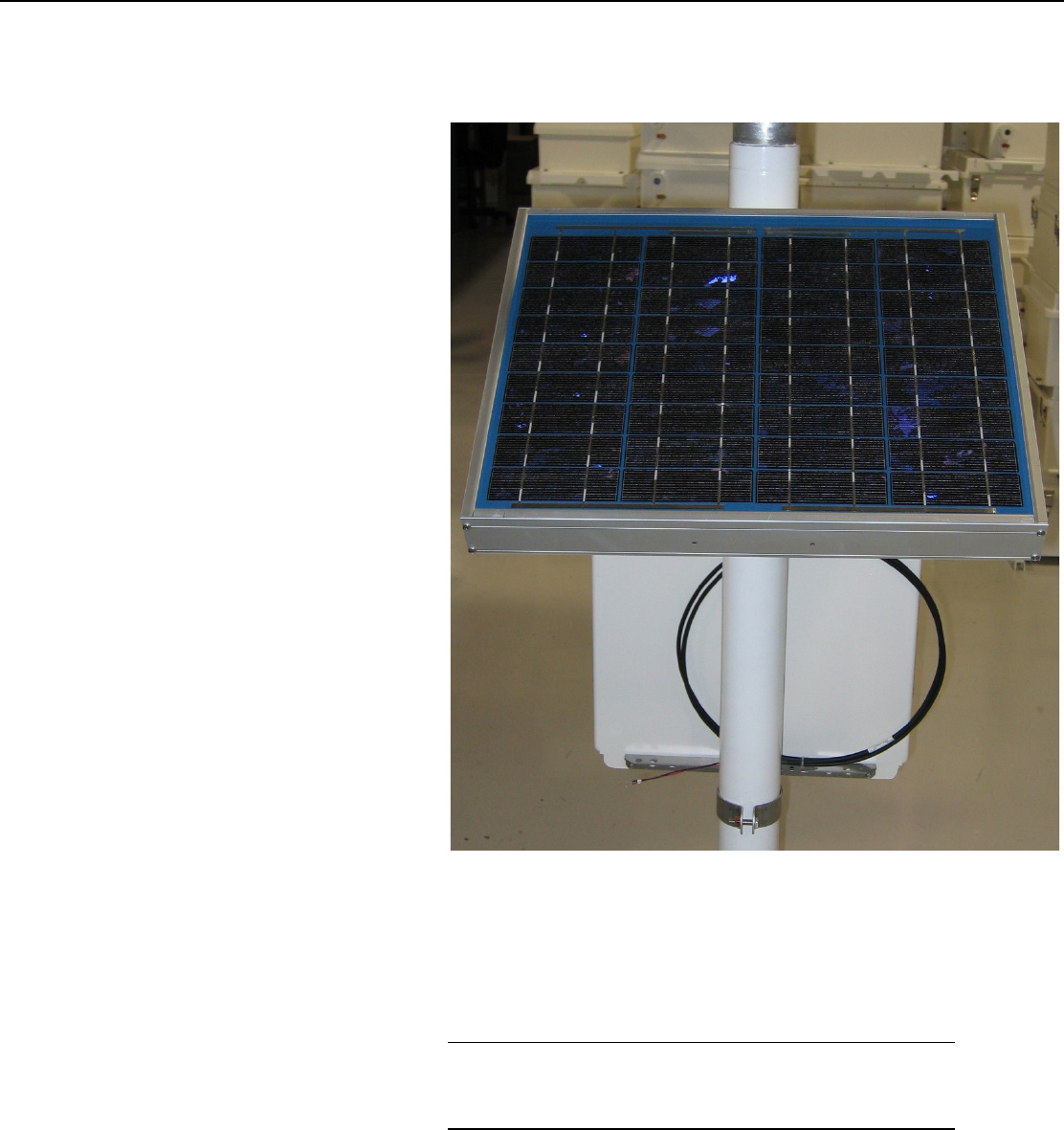
7. Install the solar panel above the 10 x 12 enclosure, and face the solar panel
south. See FIGURE B-9 for fully mounted solar.
FIGURE B-9. Mounted Solar Panel
8. Throw a blanket or box over the solar panel to prevent any voltage output.
9. Route the solar panel cable and power cable coming from the main T107
enclosure into the conduit at the bottom of the 10 x 12 enclosure.
Leave a loop of all cables under the 10 x 12 enclosure to act as a
drip line. Cut both cables to whatever length you need. It doesn’t
hurt to leave a loop of cable inside the enclosure.
IMPORTANT
B-9