
Owner's manual
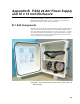
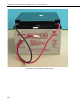

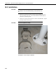

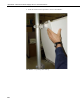

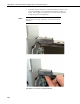
Table Of Contents
- Revision and Copyright Information
- Limited Warranty
- Assistance
- Table of Contents
- 1. Preparation and Siting
- 2. Hardware Installation
- 2.1 Base Foundation
- 2.2 Tower/Pole
- 2.3 Enclosure
- 2.4 Crossarm and Sensor Installation
- 2.5 Communication Peripherals
- 2.6 Lightning Rod Installation
- 2.7 Solar Panel Installation
- 2.8 Battery Installation
- 2.9 Restraining Cables and Sealing/Desiccating Enclosure
- 3. ET Software
- 4. Maintenance, Troubleshooting, and Schematics
- 4.1 Maintenance
- 4.2 Troubleshooting
- 4.2.1 No Response Using the CR1000KD Keypad
- 4.2.2 No Response from Datalogger through SC32B, RAD Modem, or Phone Modem
- 4.2.3 NAN or (INF Displayed in a Variable
- 4.2.4 Unreasonable Results Displayed in a Variable
- 4.2.5 NAN or (INF Stored in a Data Table
- 4.2.6 Communication Problems when using an RF450 Radio
- 4.2.7 Gill WindSonic1-ET Diagnostic Diagnostic Codes
- 4.3 Schematics of Connectors
- Appendix A. T107 Maintenance Log
- Appendix B. PS24 24 Ahr Power Supply and 10 x 12 inch Enclosure
- Appendix C. Exploded Views
- Appendix D. Default Programs
- Appendix E. Step-down Transformer Installation
- Campbell Scientific Companies
Appendix B. PS24 24 Ahr Power Supply
and 10 x 12 inch Enclosure
The PS24 Power Supply is typically used when the T107 transmits data via
RF450 Spread Spectrum Radios. However, the PS24 can be used for any
situation where a larger capacity battery is desirable.
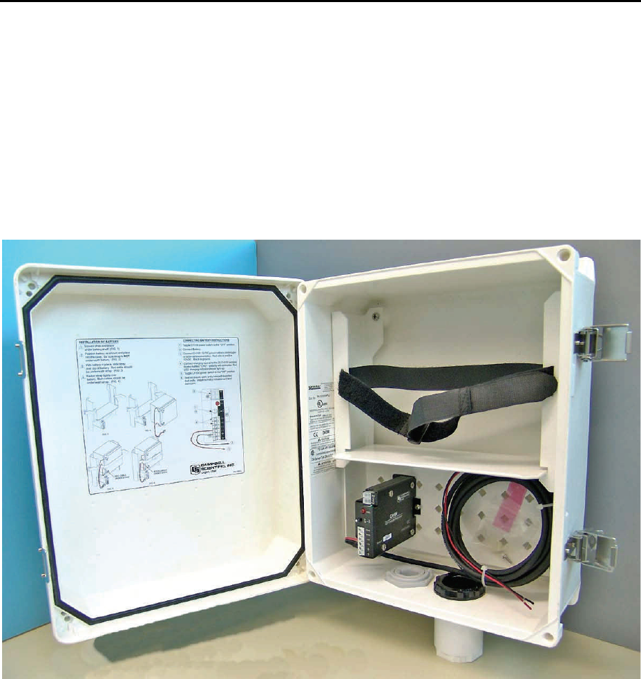
B.1 S24 Components
The PS24 consists of a 24 Ahr rechargeable battery, CH100 regulator, and a 10
inch x 12 inch environmental enclosure (see FIGURE B-1 through FIGURE
B-3). The battery should be recharged via ac power or solar power. An SP10
10-W solar panel, SP20 20-W solar panel, or 14014 Wall Charger is typically
used to recharge the battery. The environmental enclosure is mounted to the
T107’s pole using the pn 18520 hanger kit.
FIGURE B-1. Environmental Enclosure with CH100, Power Cable, and
Battery Bracket
B-1