
Owner's manual


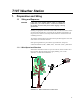
Table Of Contents
- Revision and Copyright Information
- Limited Warranty
- Assistance
- Table of Contents
- 1. Preparation and Siting
- 2. Hardware Installation
- 2.1 Base Foundation
- 2.2 Tower/Pole
- 2.3 Enclosure
- 2.4 Crossarm and Sensor Installation
- 2.5 Communication Peripherals
- 2.6 Lightning Rod Installation
- 2.7 Solar Panel Installation
- 2.8 Battery Installation
- 2.9 Restraining Cables and Sealing/Desiccating Enclosure
- 3. ET Software
- 4. Maintenance, Troubleshooting, and Schematics
- 4.1 Maintenance
- 4.2 Troubleshooting
- 4.2.1 No Response Using the CR1000KD Keypad
- 4.2.2 No Response from Datalogger through SC32B, RAD Modem, or Phone Modem
- 4.2.3 NAN or (INF Displayed in a Variable
- 4.2.4 Unreasonable Results Displayed in a Variable
- 4.2.5 NAN or (INF Stored in a Data Table
- 4.2.6 Communication Problems when using an RF450 Radio
- 4.2.7 Gill WindSonic1-ET Diagnostic Diagnostic Codes
- 4.3 Schematics of Connectors
- Appendix A. T107 Maintenance Log
- Appendix B. PS24 24 Ahr Power Supply and 10 x 12 inch Enclosure
- Appendix C. Exploded Views
- Appendix D. Default Programs
- Appendix E. Step-down Transformer Installation
- Campbell Scientific Companies

Table of Contents
C. Exploded Views ...................................................... C-1
C.1 Enclosure .......................................................................................... C-1
C.2 Crossarm .......................................................................................... C-2
D. Default Programs .................................................... D-1
D.1 Program for T107 with 034B .......................................................... D-1
D.2 Program for T107 with Gill WindSonic .......................................... D-4
E. Step-down Transformer Installation ..................... E-1
Figures
1-1. Effect of Structure on Wind Flow ........................................................ 1
1-2. Cut Flap Packing Tape ......................................................................... 3
1-3. Shipping Box Packaging ...................................................................... 3
1-4. T107 with the Met One 034B-ETM Wind Sensor, Top Layer ............. 4
1-5. T107, Bottom Layer ............................................................................. 4
1-6. Magnetic Declination for the Contiguous United States ...................... 7
1-7. Declination Angles East of True North Are Subtracted From 0 to
Get True North ................................................................................. 8
1-8. Declination Angles West of True North Are Added to 0 to Get
True North ........................................................................................ 8
2-1. ET tower installation with currently-available AC power option ...... 10
2-2. ET Tower Base Installation ................................................................ 12
2-3. Cut-Away View Shows Anchor Bolt and Conduit Placement in
Cement Pad ..................................................................................... 12
2-4. Transparent View Shows Raising and Grounding the ET Tower ...... 14
2-5. Close up of Ground Rod and 4 AWG Cable ...................................... 15
2-6. T107 Instrumentation Mounted on the ET Tower .............................. 16
2-7. Enclosure Spacing Above Pole .......................................................... 17
2-8. T107 Sensor Arm Mounting .............................................................. 18
2-9. Temperature/Relative Humidity Sensor with Yellow Protective
Cap .................................................................................................. 19
2-10. Temperature/Relative Humidity Sensor without Yellow Protective
Cap .................................................................................................. 20
2-11. Wind and RH/Temperature Sensor Installation ................................. 21
2-12. 034B Mounting to Pipe ...................................................................... 21
2-13. Screws that Secure the Electronics Cover .......................................... 23
2-14. Removal of the Electronics Cover ...................................................... 23
2-15. Jumper Set for WindSonic1 ............................................................... 24
2-16. Gill WindSonic Mounting Shaft ........................................................ 25
2-17. Gill WindSonic Connected to Cable .................................................. 25
2-18. Remove Rubber Band from Tipping Mechanism .............................. 26
2-19. Pyranometer Leveling ........................................................................ 27
2-20. Remove Red or Green Pyranometer Cap ........................................... 27
2-21. Position of Sensor Bulkhead Connectors ........................................... 28
2-22. Connecting Sensor Cabling to Enclosure ........................................... 29
2-23. Close-up of the terminals and 9-pin ports in the T107 (battery not
shown). ........................................................................................... 31
2-24. Phone Modem Mounting and Connections (battery not shown) ........ 32
2-25. Short-haul modem mounting and connection ..................................... 34
2-26. Short-Haul Modem Wiring Diagram ................................................. 36
2-27. RF450 in T107 (battery not shown) ................................................... 38
2-28. Attach Ribbon Cable to RF450 CS I/O Port ...................................... 38
iii