
Owner's manual


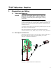
Table Of Contents
- Revision and Copyright Information
- Limited Warranty
- Assistance
- Table of Contents
- 1. Preparation and Siting
- 2. Hardware Installation
- 2.1 Base Foundation
- 2.2 Tower/Pole
- 2.3 Enclosure
- 2.4 Crossarm and Sensor Installation
- 2.5 Communication Peripherals
- 2.6 Lightning Rod Installation
- 2.7 Solar Panel Installation
- 2.8 Battery Installation
- 2.9 Restraining Cables and Sealing/Desiccating Enclosure
- 3. ET Software
- 4. Maintenance, Troubleshooting, and Schematics
- 4.1 Maintenance
- 4.2 Troubleshooting
- 4.2.1 No Response Using the CR1000KD Keypad
- 4.2.2 No Response from Datalogger through SC32B, RAD Modem, or Phone Modem
- 4.2.3 NAN or (INF Displayed in a Variable
- 4.2.4 Unreasonable Results Displayed in a Variable
- 4.2.5 NAN or (INF Stored in a Data Table
- 4.2.6 Communication Problems when using an RF450 Radio
- 4.2.7 Gill WindSonic1-ET Diagnostic Diagnostic Codes
- 4.3 Schematics of Connectors
- Appendix A. T107 Maintenance Log
- Appendix B. PS24 24 Ahr Power Supply and 10 x 12 inch Enclosure
- Appendix C. Exploded Views
- Appendix D. Default Programs
- Appendix E. Step-down Transformer Installation
- Campbell Scientific Companies

Table of Contents
2.5.3 Short-Haul Modem ..................................................................... 33
2.5.3.1 Internal Installation .......................................................... 34
2.5.3.2 External Installation ......................................................... 35
2.5.4 RF450 900 MHz, 1 Watt Spread Spectrum Radio ..................... 36
2.5.4.1 Power Considerations ...................................................... 36
2.5.4.2 Default Configuration ...................................................... 37
2.5.4.3 Internal Installation .......................................................... 37
2.5.4.4 External Installation ......................................................... 39
2.5.4.5 Base Radio Installation .................................................... 45
2.6 Lightning Rod Installation ................................................................. 47
2.7 Solar Panel Installation ...................................................................... 49
2.8 Battery Installation ............................................................................ 51
2.9 Restraining Cables and Sealing/Desiccating Enclosure .................... 52
2.9.1 Restraining Cables ...................................................................... 52
2.9.2 Sealing and Desiccating the Enclosure ....................................... 53
3. ET Software ............................................................... 54
4. Maintenance, Troubleshooting, and Schematics ... 55
4.1 Maintenance ...................................................................................... 55
4.1.1 Pole ............................................................................................. 55
4.1.2 Power Supply ............................................................................. 55
4.1.2.1 Batteries ........................................................................... 55
4.1.2.2 Solar Panel ....................................................................... 55
4.1.3 Desiccant .................................................................................... 56
4.1.4 Sensor Maintenance ................................................................... 56
4.1.4.1 Procedure for Removing RH Chip................................... 58
4.1.5 CR1000M Module ...................................................................... 58
4.2 Troubleshooting ................................................................................. 59
4.2.1 No Response Using the CR1000KD Keypad ............................. 59
4.2.2 No Response from Datalogger through SC32B, RAD
Modem, or Phone Modem ..................................................... 60
4.2.3 NAN or ±INF Displayed in a Variable ....................................... 60
4.2.4 Unreasonable Results Displayed in a Variable ........................... 61
4.2.5 NAN or ±INF Stored in a Data Table......................................... 61
4.2.6 Communication Problems when using an RF450 Radio ............ 61
4.2.7 Gill WindSonic1-ET Diagnostic Diagnostic Codes ................... 63
4.3 Schematics of Connectors ................................................................. 64
4.3.1 Sensor Schematics ...................................................................... 64
4.3.2 Power Schematics ...................................................................... 69
4.3.3 Communication Modems Schematics ........................................ 69
Appendices
A.
T107 Maintenance Log ............................................ A-1
B. PS24 24 Ahr Power Supply and 10 x 12 inch
Enclosure .............................................................. B-1
B.1 S24 Components .............................................................................. B-1
B.2 Installation ....................................................................................... B-4
ii