
Owner's manual
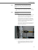


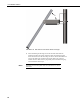
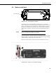
Table Of Contents
- Revision and Copyright Information
- Limited Warranty
- Assistance
- Table of Contents
- 1. Preparation and Siting
- 2. Hardware Installation
- 2.1 Base Foundation
- 2.2 Tower/Pole
- 2.3 Enclosure
- 2.4 Crossarm and Sensor Installation
- 2.5 Communication Peripherals
- 2.6 Lightning Rod Installation
- 2.7 Solar Panel Installation
- 2.8 Battery Installation
- 2.9 Restraining Cables and Sealing/Desiccating Enclosure
- 3. ET Software
- 4. Maintenance, Troubleshooting, and Schematics
- 4.1 Maintenance
- 4.2 Troubleshooting
- 4.2.1 No Response Using the CR1000KD Keypad
- 4.2.2 No Response from Datalogger through SC32B, RAD Modem, or Phone Modem
- 4.2.3 NAN or (INF Displayed in a Variable
- 4.2.4 Unreasonable Results Displayed in a Variable
- 4.2.5 NAN or (INF Stored in a Data Table
- 4.2.6 Communication Problems when using an RF450 Radio
- 4.2.7 Gill WindSonic1-ET Diagnostic Diagnostic Codes
- 4.3 Schematics of Connectors
- Appendix A. T107 Maintenance Log
- Appendix B. PS24 24 Ahr Power Supply and 10 x 12 inch Enclosure
- Appendix C. Exploded Views
- Appendix D. Default Programs
- Appendix E. Step-down Transformer Installation
- Campbell Scientific Companies
T107 Weather Station
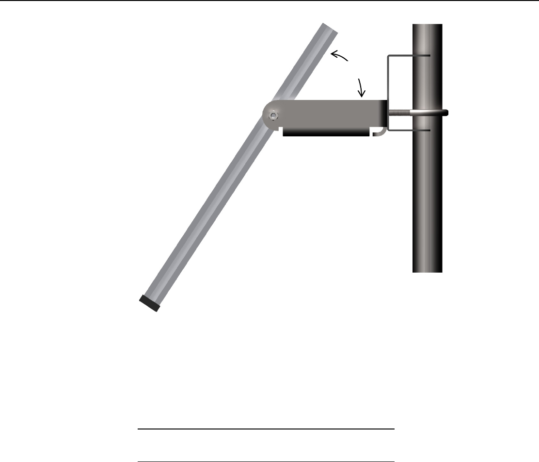
FIGURE 2-42. Side View of Solar Panel Shows Tilt Angle
b) After determining the tilt angle, loosen the two bolts that attach the
mounting bracket to the panel. Adjust the angle, then tighten the bolts.
Secure the lead wire to the mast using wire ties as show in FIGURE 2-42.
Connect the plug at the end of the solar panel cable to the connector
marked “Power”. Make sure the plug is fully seated and the locking ring
turned clockwise until it stops.
Schematics for the solar panel cable are in Section 4.3.2
, Power
Schematics.
NOTE
α
50