
Owner's manual
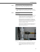


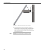
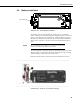
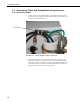
Table Of Contents
- Revision and Copyright Information
- Limited Warranty
- Assistance
- Table of Contents
- 1. Preparation and Siting
- 2. Hardware Installation
- 2.1 Base Foundation
- 2.2 Tower/Pole
- 2.3 Enclosure
- 2.4 Crossarm and Sensor Installation
- 2.5 Communication Peripherals
- 2.6 Lightning Rod Installation
- 2.7 Solar Panel Installation
- 2.8 Battery Installation
- 2.9 Restraining Cables and Sealing/Desiccating Enclosure
- 3. ET Software
- 4. Maintenance, Troubleshooting, and Schematics
- 4.1 Maintenance
- 4.2 Troubleshooting
- 4.2.1 No Response Using the CR1000KD Keypad
- 4.2.2 No Response from Datalogger through SC32B, RAD Modem, or Phone Modem
- 4.2.3 NAN or (INF Displayed in a Variable
- 4.2.4 Unreasonable Results Displayed in a Variable
- 4.2.5 NAN or (INF Stored in a Data Table
- 4.2.6 Communication Problems when using an RF450 Radio
- 4.2.7 Gill WindSonic1-ET Diagnostic Diagnostic Codes
- 4.3 Schematics of Connectors
- Appendix A. T107 Maintenance Log
- Appendix B. PS24 24 Ahr Power Supply and 10 x 12 inch Enclosure
- Appendix C. Exploded Views
- Appendix D. Default Programs
- Appendix E. Step-down Transformer Installation
- Campbell Scientific Companies
T107 Weather Station
FIGURE 2-36. Wire Tie Locations for Omni Antenna Installation
2.5.4.5 Base Radio Installation
The base radio kit comes with the following items.
(1) 10873 RS-232 Serial Data Cable with 6 feet of cable
(1) 15966 Wall Adapter: 100 to 240 Vac, 50-60 Hz Input to 12 Vdc 80 0mA
Output with 6 feet of cable.
(1) 18327 RF450 900 MHz, 1 W Spread Spectrum Radio
(1) 20617 900 MHz 0 dBd Omnidirectional Window Mount Antenna with 79
inches (6.58 feet) of Cable
The RF450 radio will need to be connected to a RS-232 serial port on the
calling computer and powered by the wall adapter. The antenna is designed to
stick to a window facing the weather station (see FIGURE 2-37 and FIGURE
2-38).
In order to comply with the FCC RF exposure requirements,
the RF450 series may be used only with approved
antennas that have been tested with this radio and a
minimum separation distance of 8 inches (20 cm) must be
maintained from the antenna to any nearby persons.
Attach the SMA connector on the antenna to the RF450 radio. Remove the
strip covering the adhesive on the antenna and stick it vertically to a window.
CAUTION
Wire Tie
Wire Tie
45