
Owner's manual
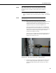


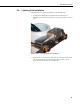


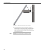
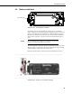
Table Of Contents
- Revision and Copyright Information
- Limited Warranty
- Assistance
- Table of Contents
- 1. Preparation and Siting
- 2. Hardware Installation
- 2.1 Base Foundation
- 2.2 Tower/Pole
- 2.3 Enclosure
- 2.4 Crossarm and Sensor Installation
- 2.5 Communication Peripherals
- 2.6 Lightning Rod Installation
- 2.7 Solar Panel Installation
- 2.8 Battery Installation
- 2.9 Restraining Cables and Sealing/Desiccating Enclosure
- 3. ET Software
- 4. Maintenance, Troubleshooting, and Schematics
- 4.1 Maintenance
- 4.2 Troubleshooting
- 4.2.1 No Response Using the CR1000KD Keypad
- 4.2.2 No Response from Datalogger through SC32B, RAD Modem, or Phone Modem
- 4.2.3 NAN or (INF Displayed in a Variable
- 4.2.4 Unreasonable Results Displayed in a Variable
- 4.2.5 NAN or (INF Stored in a Data Table
- 4.2.6 Communication Problems when using an RF450 Radio
- 4.2.7 Gill WindSonic1-ET Diagnostic Diagnostic Codes
- 4.3 Schematics of Connectors
- Appendix A. T107 Maintenance Log
- Appendix B. PS24 24 Ahr Power Supply and 10 x 12 inch Enclosure
- Appendix C. Exploded Views
- Appendix D. Default Programs
- Appendix E. Step-down Transformer Installation
- Campbell Scientific Companies
T107 Weather Station
Only rotate enclosure if needed to allow aiming of the Yagi
antenna to the base antenna. Keep solar radiation sensor towards
the South as much as possible. Rotate wind sensor to realign as
needed.
5. Use the following procedure to install the 14205 Yagi antenna for the
RF450. Installation of the 14221 Omni antenna is similar. See FIGURE
2-36.
Mounting hardware that comes in the box with the Yagi antenna
will not be used.
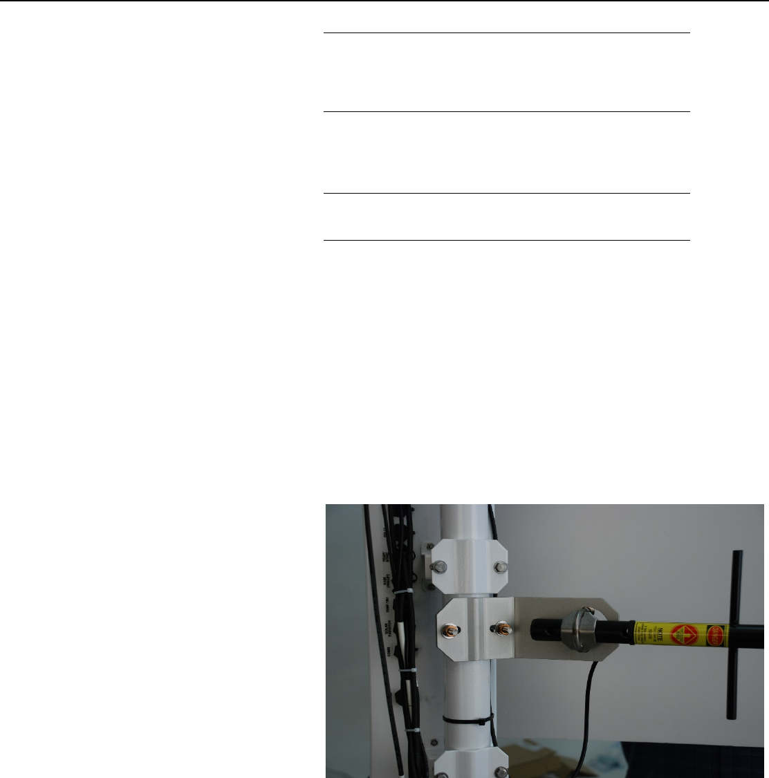
i. Slide the back of the Yagi antenna into the saddle bracket. If the
Yagi antenna at the station is communicating with an
omnidirectional antenna at the base then align the tines on the
Yagi antenna so they are vertical. See FIGURE 2-34.
If two Yagi antennas are used at both ends of communication
then align the tines the same. If interference is a concern then
align the tines on the two Yagi antennas horizontally instead of
vertically. This will put the signal out of phase with other
antennas that are aligned vertically.
Tighten the nuts on saddle bracket to hold the antenna firmly in
place. Do NOT over tighten the nuts on the saddle bracket or
damage to the antenna may occur.
FIGURE 2-34. Yagi Antenna Mounted to Saddle Bracket
ii. Orient the Yagi antenna so it’s aimed at the base antenna. You
may have to flip the adjustable angle bracket over to get the
antenna and saddle bracket to point correctly in the vertical
direction.
NOTE
NOTE
43