
Owner's manual

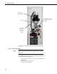

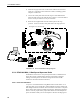


Table Of Contents
- Revision and Copyright Information
- Limited Warranty
- Assistance
- Table of Contents
- 1. Preparation and Siting
- 2. Hardware Installation
- 2.1 Base Foundation
- 2.2 Tower/Pole
- 2.3 Enclosure
- 2.4 Crossarm and Sensor Installation
- 2.5 Communication Peripherals
- 2.6 Lightning Rod Installation
- 2.7 Solar Panel Installation
- 2.8 Battery Installation
- 2.9 Restraining Cables and Sealing/Desiccating Enclosure
- 3. ET Software
- 4. Maintenance, Troubleshooting, and Schematics
- 4.1 Maintenance
- 4.2 Troubleshooting
- 4.2.1 No Response Using the CR1000KD Keypad
- 4.2.2 No Response from Datalogger through SC32B, RAD Modem, or Phone Modem
- 4.2.3 NAN or (INF Displayed in a Variable
- 4.2.4 Unreasonable Results Displayed in a Variable
- 4.2.5 NAN or (INF Stored in a Data Table
- 4.2.6 Communication Problems when using an RF450 Radio
- 4.2.7 Gill WindSonic1-ET Diagnostic Diagnostic Codes
- 4.3 Schematics of Connectors
- Appendix A. T107 Maintenance Log
- Appendix B. PS24 24 Ahr Power Supply and 10 x 12 inch Enclosure
- Appendix C. Exploded Views
- Appendix D. Default Programs
- Appendix E. Step-down Transformer Installation
- Campbell Scientific Companies
T107 Weather Station
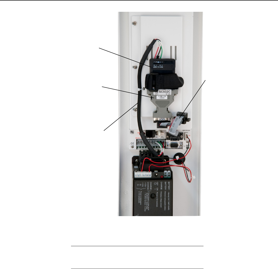
FIGURE 2-25. Short-haul modem mounting and connection
2.5.3.1 Internal Installation
If the short haul modem was ordered with the T107, you can skip
this section and go directly to Section 2.5.3.2, External
Installation.
For installation inside the ET Enclosure, the following components are
provided in the short-haul modem kit:
(1) Part number 10596 (SC932C) 9-pin to RS-232 DCE Interface
(1) Rad Modem
(1) Rad/SC932C Mounting Bracket
(1) 12 inch 4-wire patch cable
NOTE
Rad Short
Haul Modem
SC932C
12” 4-Wire
Patch Cable
(see Figure
2.5-4 for
wiring)
10588 Ribbon Cable
(see Figure 2.5
-4 for
wiring)
34