
Owner's manual
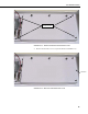
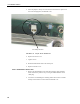
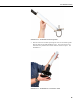
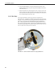
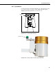
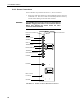
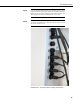

Table Of Contents
- Revision and Copyright Information
- Limited Warranty
- Assistance
- Table of Contents
- 1. Preparation and Siting
- 2. Hardware Installation
- 2.1 Base Foundation
- 2.2 Tower/Pole
- 2.3 Enclosure
- 2.4 Crossarm and Sensor Installation
- 2.5 Communication Peripherals
- 2.6 Lightning Rod Installation
- 2.7 Solar Panel Installation
- 2.8 Battery Installation
- 2.9 Restraining Cables and Sealing/Desiccating Enclosure
- 3. ET Software
- 4. Maintenance, Troubleshooting, and Schematics
- 4.1 Maintenance
- 4.2 Troubleshooting
- 4.2.1 No Response Using the CR1000KD Keypad
- 4.2.2 No Response from Datalogger through SC32B, RAD Modem, or Phone Modem
- 4.2.3 NAN or (INF Displayed in a Variable
- 4.2.4 Unreasonable Results Displayed in a Variable
- 4.2.5 NAN or (INF Stored in a Data Table
- 4.2.6 Communication Problems when using an RF450 Radio
- 4.2.7 Gill WindSonic1-ET Diagnostic Diagnostic Codes
- 4.3 Schematics of Connectors
- Appendix A. T107 Maintenance Log
- Appendix B. PS24 24 Ahr Power Supply and 10 x 12 inch Enclosure
- Appendix C. Exploded Views
- Appendix D. Default Programs
- Appendix E. Step-down Transformer Installation
- Campbell Scientific Companies
T107 Weather Station
2.5.2 Phone Modem
Phone modems enable communications between the ET Enclosure and a Hayes
compatible modem at your PC over a dedicated phone line. Phone line surge
protection is built into the ET Enclosure. By default, the COM220 phone
modem is configured for SDC7.
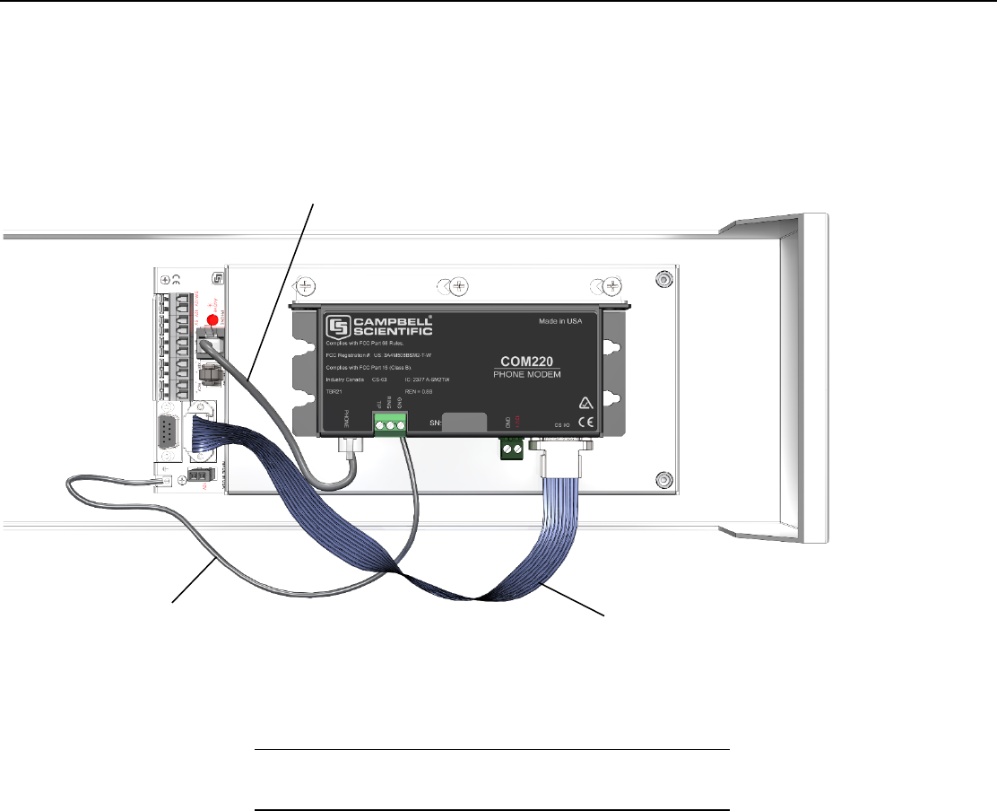
FIGURE 2-24. Phone Modem Mounting and Connections (battery not
shown)
2.5.2.1 Internal Installation
If the phone modem was ordered with the T107, you can skip this
section and go directly to Section 2.5.2.2, External Installation.
For installation inside the ET Enclosure, the following components are
provided in the phone modem kit:
(1) COM220 Phone Modem
(1) 12 inch RJ-11 Patch Cord
(1) Mounting Bracket
(4) Screws
(1) 12 inch 14 AWG Ground Wire
Install the phone modem as shown in FIGURE 2-24.
1. Attach the modem to the modem bracket with the 2 screws provided.
Mount the modem and bracket into the ET Enclosure with the 3 pre-
threaded screws on the mounting plate.
NOTE
RJ-11 Patch Cord Connects with RJ-11 Jack
10588 Ribbon Cable
Ground Wire
32