
Owner's manual


Table Of Contents
- Revision and Copyright Information
- Limited Warranty
- Assistance
- Table of Contents
- 1. Preparation and Siting
- 2. Hardware Installation
- 2.1 Base Foundation
- 2.2 Tower/Pole
- 2.3 Enclosure
- 2.4 Crossarm and Sensor Installation
- 2.5 Communication Peripherals
- 2.6 Lightning Rod Installation
- 2.7 Solar Panel Installation
- 2.8 Battery Installation
- 2.9 Restraining Cables and Sealing/Desiccating Enclosure
- 3. ET Software
- 4. Maintenance, Troubleshooting, and Schematics
- 4.1 Maintenance
- 4.2 Troubleshooting
- 4.2.1 No Response Using the CR1000KD Keypad
- 4.2.2 No Response from Datalogger through SC32B, RAD Modem, or Phone Modem
- 4.2.3 NAN or (INF Displayed in a Variable
- 4.2.4 Unreasonable Results Displayed in a Variable
- 4.2.5 NAN or (INF Stored in a Data Table
- 4.2.6 Communication Problems when using an RF450 Radio
- 4.2.7 Gill WindSonic1-ET Diagnostic Diagnostic Codes
- 4.3 Schematics of Connectors
- Appendix A. T107 Maintenance Log
- Appendix B. PS24 24 Ahr Power Supply and 10 x 12 inch Enclosure
- Appendix C. Exploded Views
- Appendix D. Default Programs
- Appendix E. Step-down Transformer Installation
- Campbell Scientific Companies
Appendix E. Step-down Transformer
Installation
This appendix is for users who have a step-down transformer instead of the 100 to 240 Vac
to 24 Vdc power supply.
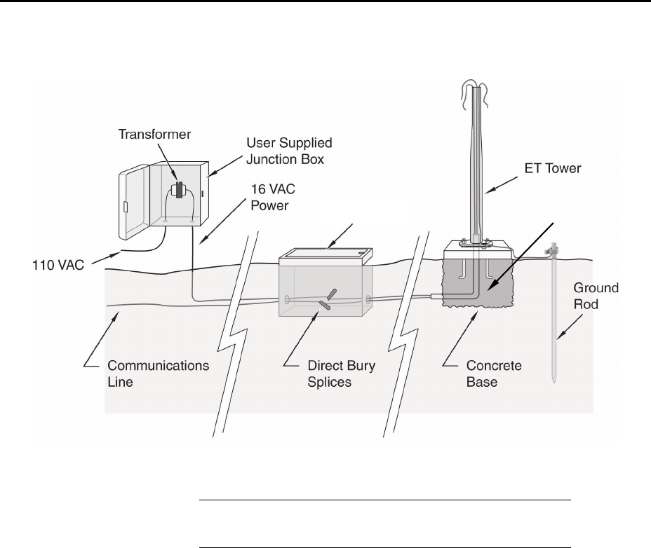
FIGURE E-1. ET tower installation with step-down transformer
User supplies valve box at base of station and weatherproof
enclosure for transformer. See FIGURE E-1.
1. The AC power option at one time included a 120 Vac to 16 Vac step-down
transformer. The transformer should be mounted inside a user-supplied
junction box according to local electrical codes. Dangerous electrical
accidents may be avoided by locating the transformer remotely and
burying a low voltage line to the station. The low voltage will carry up to
500 feet on an 18 AWG power cable.
2. Shut off 110 Vac power at the main breaker. Connect the primary leads of
the transformer to 110 Vac following instructions provided with the
transformer. Connect a two-conductor cable to the secondary terminals of
the transformer. Route the cable from the transformer to the ET Enclosure
according to local electrical codes.
3. Splice the incoming two-conductor cable to the power cable provided with
the station. Use the direct burial splice kit when splices are in a valve box
or buried.
NOTE
Swept Elbow
Conduit
User-Supplied
Valve Box
E-1