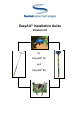
EasyAG® Installation Guide Version 3.
EasyAG® Installation Guide EasyAG® 50 EasyAG® 80 All rights reserved. No part of this document may be reproduced, transcribed, translated into any language or transmitted in any form electronic or mechanical for any purpose whatsoever without the prior written consent of Sentek Pty Ltd. All intellectual and property rights remain with Sentek Pty Ltd. All information presented is subject to change without notice. Names of programs and computer systems are registered trademarks of their respective companies.
EasyAG Installation Guide Versio n 3.
EasyAG Installation Guide Versio n 3.0 Low Resolutio n About this manual This guide describes the principles of site selection and the materials and methods that are used to install Sentek EasyAG probes. Document Conventions Before you start it is important that you understand the conventions used in this manual.
Introduction Introduction The EasyAG Installation Guide provides important information about how to select monitoring sites and install access tubes. Site selection and access tube installation have a significant impact on the value of the soil moisture data that can be gathered on your property.
Site Selection Site Selection The key to effective soil moisture monitoring is to select monitoring sites which truly represent irrigation management areas where crop water use and soil water storage are similar. The same basic site selection principles apply to the full range of Sentek soil moisture monitoring devices. Many variables influence the spatial distribution of water across an area of land. These variables and their impact on site selection are discussed in more detail below.
Site Selection Crop water use is governed by many factors such as soil properties, crop stage, water quality, weather patterns and type of irrigation system. These factors need to be considered when defining the macro zones on your property and are described in the following pages. Micro zone selection determines the position of access tubes in relation to the crop and irrigation system.
Site Selection Rainfall Rain is generally associated with higher humidity levels and lower solar radiation and temperatures. It follows that days on which rainfall occurs are associated with lower water demand and use than dry sunny days. Notwithstanding the care taken to delineate macro zones, some variability in soil moisture levels is inevitable. For example: on large properties, rain events may cover only a portion of the land area, replenishing some soil reservoirs and leaving others dry.
Site Selection Organic Matter The presence of organic matter and humus increases the cation exchange capacity (CEC), water holding capacity and structural stability of soils. This influence is predominantly in the top soil, although lamellae (thin organic matter layers further down the profile) can be important properties. Soil che mistry Acid, alkaline, sodic (soils characterized by a dominance of sodium ions) or nutrient deficient conditions impact on expected soil chemical properties.
Site Selection Mulch can improve the infiltration rate of the soil, reduce water run-off, encourage root growth near the soil surface and increase the soil water holding capacity over time, through the accumulation of soil organic matter, and reduce soil temperature. Oil spraying Oily substances on leaves reduce water use by temporarily closing stomata. An example of this is mite control in citrus.
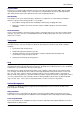
Site Selection Firstly the soil properties and types are considered, to differentiate between areas of varying soil-water properties: Then the soil limitations and suitability for the proposed are identified in order to determine the need for soil improvements and amelioration: Copyright © 1991 – 2003 Sent ek Pt y Lt d All rights res erved Page 8
Site Selection From this the requirements for soil improvements and amelioration are outlined: Once the soil has been ameliorated and improved then the altered soil properties are considered in conjunction with the topography, irrigation system and crop types to delineate irrigation management units.
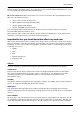
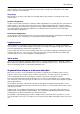
Site Selection Overlaying all this information makes it possible to identify, within a property, areas (zones) that have significantly different requirements. In the example used, the property has been divided into eight macro zones. Each macro zone requires a monitoring site. Potential sites are shown by the dots, but final positioning can be determined by the information in the micro scale zone selection.
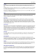
Site Selection This information is then plotted as shown in the example below. Cans in the blue shaded area received above average water; those in the red shading below average; while those in the green shaded area received an average amount. Due to the specific nature of each site in terms of irrigation system, it is inappropriate to give prescriptive advice on probe placement. For soil moisture monitoring, it should however, be representative and consistent.
Site Selection In addition, in drip irrigation, the slope needs to be taken into consideration, to account for movement of water down slope. In furrow irrigated fields, probes should be installed 50 to 100 metres away from the head ditch. Probes should not be installed at the opposite side to the head ditch, as tail water from the irrigation may back up the furrows and give unrepresentative readings.
Installing EasyAG probes Installing EasyAG probes Safety Sentek encourages the use of safe practices that minimize the risks to users, their machinery and their property. The following safety information is provided to help prevent accidents during installation. Carrying the equipment into the field Some of the equipment used in this procedure is heavy. Care must be taken when carrying it into the field for the installation, such that muscle and back injuries are avoided.
Installing EasyAG probes Items required for installation Sentek Items EasyAG 50 Probe Complete 5 wire interface Voltage interface SDI-12 interface RS232 interface RS485 interface EasyAG Installation Kit includes the following: 1 x stabilization plate 1 x polyguide, stabilization plate 4 x stabilization plate pins (long) 4 x stabilization plate pins (short) 1 x EasyAG dolly 1 x dolly rubber Copyright © 1991 – 2003 Sent ek Pt y Lt d All rights res erved Description EasyAG probe that connects to an
Installing EasyAG probes 1.1 metre AMS soil sampling auger and cleaning tool 1 x EasyAG extraction tool (optional item) The AMS Soil sampling auger is used to pre-drill a slightly undersized hole for insertion of the EasyAG 50 and EasyAG 80 probes The EasyAG extraction tool assist s in the removal of EasyAG probes plastics from the ground. The tool is used to grip the probe plastics for attachment to a winch, jack, hydraulic lifting device, or similar.
Installing EasyAG 50 probes Installing EasyAG 50 probes Step 1 - Assembling the stabilization plate The stabilization plate can be used on both flat ground and raised soil beds. There are two different types of stabilization plate pins for this reason: a short pin for flat ground and a long one for raised soil beds. Step 2 - (option A) Fixing the stabilization plate on flat ground 1. Place the stabilization plate on the ground where the probe is to be situated. 2.
Installing EasyAG 50 probes 3. Apply gentle pressure directly down onto the stabilization plate to force the pins into the ground. Ensure that the stabilization plate pins remain parallel to one another. 4. Using a sledgehammer alternately beat the stabilization plate at the points provided to force it closer to the ground. Do not beat continuously on any one side in advance of the other. The aim is to achieve a situation where the pins are near parallel in the ground. 9 5.
Installing EasyAG 50 probes 6. Insert the soil sampler polyguide. The stabilization plate is now ready for insertion of the AMS soil sampler. Step 3: Preparing the hole 1. Insert the AMS soil sampler and force downward in a single smooth action by hand until the resistance becomes too great. 2. Using a sledgehammer, beat the AMS soil sampler into the ground until the bottom of the beating head sits 25 cm above the stabilization plate.
Installing EasyAG 50 probes 3. Turn the AMS soil sampler one single complete rotation clockwise. 4. Carefully lift the AMS soil sampler directly out of the ground. To remove the soil collected in the soil sampler, simply beat on its side with the hand or foot. The design is such that the soil core taken is slightly compressed, and of a lesser internal diameter than the soil sampler itself.
Installing EasyAG 50 probes Step 5 - Inserting the access tube 1. Insert the assembled complete probe into the stabilization plate and push it into the ground in a single gentle movement as far as it will go. Do not cause undue inflection of the access tube, as this will destroy the integrity of the installation. 2. As the probe enters the prepared hole in the soil, it shaves off a soil residue that is eventually stored in the cutting tip or falls to the bottom of the hole. 3.
Installing EasyAG 50 probes 5. Feed the cable through the FairRite bead and the cable gland into the top cap. It is simpler to push the cable through the cable gland at this point than when the access tube is installed in the ground. 6. Remove the stabilization plate wing nuts. 7. Remove the stabilization plate pins and separate the 2 halves of the stabilization plate and remove them. 8.
Installing EasyAG 50 probes Step 6 – Fitting the top cap lid 1. Carefully slide the probe into the access tube, ensuring that the top of the probe seats correctly into the grooves in the top cap. Connect the cable to the green phoenix connector on the top of the probe. Refer to the EasyAG Hardware Manual for wiring instructions for the specific probe interface. 2. Pull the excess cable back through the cable gland.
Installing EasyAG 50 probes 4. Tighten the FairRite bead into position and tighten the cable gland. The probe is now installed and upon connection to the data logger is ready for use.
Installing EasyAG 80 probes Installing EasyAG 80 probes Step 1 - Assembling the stabilization plate The stabilization plate can be used on both flat ground and raised soil beds. There are two different types of stabilization plate pins for this reason: a short pin for flat ground and a long one for raised soil beds. The methodology of assembling the stabilization plate is identical to that used for the EasyAG 50 probe. Step 2 - (option A) Fixing the stabilization plate on flat ground 1.
Installing EasyAG 80 probes Step 2 (option B) Fixing the stabilization plate to a raised soil bed 7. Insert each of the four long stabilization plate pins into the holes in the stabilization plate and tighten the wing nuts with light finger pressure. 8. Place the assembled stabilization plate on the ground directly above the required position of the probe. 9. Apply gentle pressure directly down onto the stabilization plate to force the pins into the ground.
Installing EasyAG 80 probes 11. The stabilization plate should be firm to the ground without causing significant soil compression Warning Do not compress the soil such that normal water infiltration into the soil is likely to be inhibited. This is particularly important on clay soils. 12. Insert the soil sampler polyguide. The stabilization plate is now ready for insertion of the AMS soil sampler. Step 3: Preparing the hole 1.
Installing EasyAG 80 probes 2. Using a sledgehammer, beat the AMS soil sampler into the ground until the beating head is just above the stabilization plate. (While it is preferable to go all the way in one insertion, successful installation may be possible in heavier soils with 2 insertions). Ensure accurate blows are made such that lateral deflection of the soil sampler is minimized. Do not compress the soil with the final blow.
Installing EasyAG 80 probes Step 4 - Assembling the EasyAG probe 1. Attach the cutting tip to the base of the probe with firm pressure. No glue is required. 2. Remove the lid of the top cap and extract the electronics. Place this safely to one side on a clean, dry surface such as a tarpaulin. 3. Feed the cable through the FairRite bead and the cable gland into the top cap. It is simpler to push the cable through the cable gland at this point than when the access tube is installed in the ground.
Installing EasyAG 80 probes 3. As the probe enters the prepared hole in the soil, it shaves off a soil residue that is eventually stored in the cutting tip and at the base of the hole. 4. Slide the dolly rubber to the top of the EasyAG 80 dolly. Insert the EasyAG 80 dolly into the access tube and position it on top of the joiner at the base of the access tube. Gently slide the dolly rubber into the top cap to stabilize the EasyAG 80 dolly. 5.
Installing EasyAG 80 probes 9. Continue inserting the probe into the ground with gentle blows of the sledgehammer, whilst holding the top of the probe steady with one hand, using the EasyAG 80 dolly, until the base of the top cap is level with the ground. This will place the top sensor at 10 cm (3.9 inches) below the ground surface. Remove the EasyAG 80 dolly. Step 6 – Fitting the top cap lid 1.
Installing EasyAG 80 probes 3. Ensure that the sealing gasket on the top cap is clean, in good condition and positioned correctly, and replace the lid of the top cap. Tighten the screws evenly completely to ensure an effective seal. 4. Tighten the FairRite bead and into position and tighten the cable gland. The probe is now installed and upon connection to the data logger is ready for use.
Trouble shooting the preferred installatio n method Troubleshooting the preferred installation method A few known factors may cause anomalies in the data obtained from the EasyAG probes. The data itself gives the best indication of a potential problem.
Trouble shooting the preferred installatio n method Techniques for avoiding poor installation Soil Suitability EasyAG probes may be installed into a range of soil types ranging in texture from light sand to heavy clay. It is unsuitable for installation in stony ground, where the average stone size is greater than 10 mm. This is because large stones may damage the plastic cutting tip of the probe and divert the direction of the insertion.
Removing EasyAG access tubes Removing EasyAG access tubes Removal of access tubes is a relatively simple process in loose, sandy soils. It may be done with the electronics in place. Simply excavate some soil from around the probe, then turn the probe in the soil and pull upwards. In heavier soils, it may be necessary to excavate the soil around the probe to a greater depth before the probe can be removed by hand.
Recommended reading Recommended reading Brady, N.C., Weil, R.R. (1996). The Nature and Properties of Soils, 11th Edition, Upper Saddle River, New Jersey, USA, Prentice Hall, Inc. Burt, C.M. (1996). AG-Irrigation Management, Irrigation Training and Research Centre (ITRC), California Polytechnic State University (Cal Poly), San Luis Obispo, California, USA. Cornish, J.B., Murphy, J.P., Fowler, C.A. Eds (1990).
Acknow le dgements Acknowledgements Sentek acknowledges the significant input from the following companies and individuals in the development of the EasyAG product: AMS (Arte’s Manufacturing Supplies), Idaho, USA Boben Mladenovic, Opal Engineering, Adelaide, South Australia Trevor McGrath, Deltameter, Adelaide, South Australia Paul Huxtable, Proen, Adelaide, South Australia Hydra, Adelaide, South Australia Steven Marks, Caurnamont, South Australia John Rasic, JR’s Soil Management Services, Adelaide, South