SDS-122 Serial Data Switch 5/99 C o p y r i g h t © 1 9 9 6 - 1 9 9 9 C a m p b e l l S c i e n t i f i c , I n c .
Warranty and Assistance The SDS-122 SERIAL DATA SWITCH is warranted by CAMPBELL SCIENTIFIC, INC. to be free from defects in materials and workmanship under normal use and service for twelve (12) months from date of shipment unless specified otherwise. Batteries have no warranty. CAMPBELL SCIENTIFIC, INC.'s obligation under this warranty is limited to repairing or replacing (at CAMPBELL SCIENTIFIC, INC.'s option) defective products.
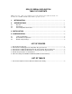
SDS-122 SERIAL DATA SWITCH TABLE OF CONTENTS PDF viewers note: These page numbers refer to the printed version of this document. Use the Adobe Acrobat® bookmarks tab for links to specific sections. 1. INTRODUCTION.........................................................................................................................1 2. SPECIFICATIONS .....................................................................................................................1 2.1 2.2 2.3 Physical.............
This is a blank page.
SDS-122 SERIAL DATA SWITCH The SDS-122 is a configurable two-way serial data switch which will allow two modem devices to be connected to a datalogger simultaneously, so allowing both remote and local interrogation of the datalogger to be carried out. It can support both DTE and DCE devices without the need for a null modem cable, and can operate either in manual or automatic mode. 1. INTRODUCTION The SDS-122 will normally be fitted in a datalogger enclosure.
SDS-122 SERIAL DATA SWITCH 2.2 OPERATIONAL TABLE 1. Current Consumption in Various Modes/Communication Activity Mode Activity Current Drain from Datalogger Isolated Quiescent (not communicating) <75µA Isolated Communicating Up to 3mA Non-Isolated No RAD-SRM modem connected and with no communication activity (quiescent) <100µA Non-Isolated RAD-SRM connected, waiting for call 2.5mA Non-Isolated RAD-SRM in comms.
SDS-122 SERIAL DATA SWITCH The switched datalogger port (marked ‘PORT B’ in Figure 1) is a 9-way female ‘D’ type connector, having the following pin configuration: Switched Datalogger Port B 5 4 9 3 8 2 7 1 6 FIGURE 3. Pin Positions for Switched Datalogger Port ‘B’: 9-way Female ‘D’ Type Connector PIN ABBREVIATION I/O 1 2 3 4 5 6 7 8 9 +5V 0V RING RX ME SDE/PE CLK/HS Not connected TX I I O O O O 25-Way Switched RS232 Port A SERIAL I/O 13 1 25 14 FIGURE 4.
SDS-122 SERIAL DATA SWITCH Control Port (3-way Screw Terminal) The control port is a 3-way terminal block with screwed connections. This terminal block can be unplugged from the unit for ease of wiring. The terminal connections are marked G, P and M and are used as follows: TERMINAL CONNECTION G 0V – It is recommended that a wire is run from this terminal to the main protective earth point in the system to give maximum protection from interference and transients.
SDS-122 SERIAL DATA SWITCH result in errors on low-level analogue measurements. The SDS-122 can be set to provide opto-isolation to prevent such ground loops, but this mode of operation is not suitable for all RS232 devices, either because the device needs to source power from the datalogger or because it is not able to provide power to the output electronics of the SDS122. power available. When this mode is enabled, no isolation is provided by the SDS-122.
SDS-122 SERIAL DATA SWITCH OPEN OPEN OPEN OPEN C109 R44 PL41 PL42 PL43 PL44 R123 R147 R124 R122 R121 U1 R142 R47 D24 R14 CONN1 R130 U6 IC1 R150 D8 C108 UB1 R43 R149 C101 R126 U8 R141 R117 R118 CONN3 R120 R119 U7 R151 D21 U4 R16 R17 D22 C110 PL56 OPEN R145 R18 D17 R7 R13 U2 2 D16 3 D23 5 6 R148 1 7 R144 10 SW6-10 DCE D10 ISOLATED R8 C3 D15 DTE SW1-5 D20 CLOSED 8 9 4 PL50 Q6 PL51 OPEN POWERED D19 D18 C111 D4 C5 R20 Q3 C112 C7 FS1 ZD1 CONN2 U5 C6
SDS-122 SERIAL DATA SWITCH OPEN OPEN OPEN OPEN C109 R44 PL41 PL42 PL43 PL44 R123 R147 R124 R122 R121 U1 R142 R47 D24 R14 CONN1 R130 U6 IC1 R150 D8 C108 UB1 R43 R149 C101 R126 U8 R141 R117 R118 CONN3 R120 R119 U7 R151 D21 U4 R16 R17 D22 C110 PL56 OPEN R145 R18 D17 R7 R13 U2 D15 DCE D10 SW6-10 D23 6 R148 7 R144 10 PL50 Q6 9 PL51 OPEN POWERED 5 1 4 DTE SW1-5 D20 CLOSED 8 3 DTE CHANGE TO POWER TURN 180” R8 ISOLATED 2 CHANGE TO C3 TURN 180” D16 D19 D18
SDS-122 SERIAL DATA SWITCH 4.3 DEFAULT JUMPER SETTINGS JUMPER DEFAULT DESCRIPTION PL41 Not fitted When jumper PL41 is fitted, port A/B on the 3-way screw terminal will output 0V for switch on port A, or 5V for switch on port B when the SDS-122 is in AUTO mode only. When the jumper is not fitted, or the unit is in MANUAL mode, then the line becomes an input. PL42 Not fitted When jumper PL42 is fitted the SDS-122 will default to the port selected by PL43 when the ME line goes low.
This is a blank page.
Campbell Scientific Companies Campbell Scientific, Inc. (CSI) 815 West 1800 North Logan, Utah 84321 UNITED STATES www.campbellsci.com info@campbellsci.com Campbell Scientific Africa Pty. Ltd. (CSAf) PO Box 2450 Somerset West 7129 SOUTH AFRICA www.csafrica.co.za sales@csafrica.co.za Campbell Scientific Australia Pty. Ltd. (CSA) PO Box 444 Thuringowa Central QLD 4812 AUSTRALIA www.campbellsci.com.au info@campbellsci.com.au Campbell Scientific do Brazil Ltda.