SDM-AO4A Four Channel Analog Output Module 5/11 C o p y r i g h t © 1 9 8 6 - 2 0 1 1 C a m p b e l l S c i e n t i f i c , I n c .
Warranty and Assistance PRODUCTS MANUFACTURED BY CAMPBELL SCIENTIFIC, INC. are warranted by Campbell Scientific, Inc. (“Campbell”) to be free from defects in materials and workmanship under normal use and service for twelve (12) months from date of shipment unless otherwise specified on the corresponding Campbell invoice. Batteries, fine-wire thermocouples, desiccant, and other consumables have no warranty.
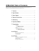
SDM-AO4A Table of Contents PDF viewers note: These page numbers refer to the printed version of this document. Use the Adobe Acrobat® bookmarks tab for links to specific sections. 1. Function........................................................................1 2. Specifications ..............................................................1 3. Power Supply ...............................................................2 4. Physical Connections .................................................2 5.
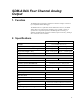
SDM-AO4A Four Channel Analog Output 1. Function The SDM-AO4A is designed to output four continuous voltages at levels set by a Campbell Scientific datalogger. The SDM-AO4A is a replacement for the SDM-AO4. However, the SDMAO4A offers several new features including a 0-10 V Mode, a choice of synchronous or sequential operation, and SDM signature checking. In addition, the SDM-AO4A has higher resolution, improved accuracy, and high drive current for sensor excitation. 2.
SDM-AO4A Four Channel Analog Output 3. Power Supply It is often convenient to power the SDM-AO4A from the datalogger power supply, but when doing so consideration must be given to the SDM-AO4A's continuous current drain (the current drain is 11 mA in ±5V mode and 21 mA in 10V mode). The alkaline supply available with the datalogger has 7.5 Amphours and will power one SDM-AO4A for less than one month. This supply is not recommended for continuous long-term operation.
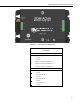
SDM-AO4A Four Channel Analog Output FIGURE 1. Front Panel of the SDM-AO4A TABLE 1.
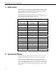
SDM-AO4A Four Channel Analog Output 5. Addressing The SDM-AO4A is a synchronously addressed datalogger peripheral. Control Ports 1, 2, and 3, are used to address an SDM-AO4A and send out the digital millivolt settings for subsequent analog output. Addressing allows multiple SDM peripherals to be connected to one datalogger. The SDM-AO4A has sixteen possible addresses, as shown in Table 2. The address is hardware selectable using the rotary switch on the SDM-AO4A.
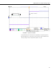
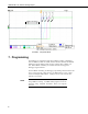
SDM-AO4A Four Channel Analog Output SDM Transmission Vout 1 to Vout 4 FIGURE 2. Synchronous Mode In sequential mode, the channels are set sequentially. The output signal can take from 600 µsecs to 1 ms (worst case) to settle to 16-bit resolution with a 10V step change. The four outputs then update 1 ms apart.
Vout 4 Vout 3 Vout 2 Vout 1 SDM-AO4A Four Channel Analog Output SDM Transmission FIGURE 3. Sequential Mode 7. Programming The datalogger is programmed using either CRBasic or Edlog. Dataloggers that use CRBasic include our CR800, CR850, CR1000, CR3000, and CR5000. Dataloggers that use Edlog include our CR7, CR10X, CR10, CR23X, and 21X. Both CRBasic and Edlog are included in PC400 and LoggerNet datalogger support software.
SDM-AO4A Four Channel Analog Output 7.1 CRBasic 7.1.1 SDMAO4A Instruction The SDMAO4A instruction is used to set the voltage to an SDM-AO4A. NOTE The SDM-AO4A is backwards compatible with the SDMAO4 CRBasic instruction. Therefore, programs written using the SDMAO4 instruction will work with an SDM-AO4A but will not take advantage of any of the SDM-AO4A’s additional features. If the older instruction is used, the device will use the default option code 1.
SDM-AO4A Four Channel Analog Output SDMAO4AOption: The SDMAO4AOption parameter is used to set the operating mode for the SDMAO4A. Option Code 0 1 2 3 4 Description Power down 5V synchronous 5V sequential 10V synchronous 10V sequential In the synchronous mode, all channels are set at the same time. This mode is slower since for large changes in voltage it may take multiple charging cycles to arrive at the final voltage.
SDM-AO4A Four Channel Analog Output Equation for CR800, CR850, and CR1000: bit_rate=INT((k*72)/625)*Resolution Where: k= the value entered in BitPeriod Resolution=8.68 microseconds Equation for CR3000: bit_rate=INT((k*144)/625)*Resolution Where: k= the value entered in BitPeriod Resolution= 4.34 μsec. Equation for CR5000: bit_rate=INT(k*20)*Resolution Where: k= the value entered in BitPeriod Resolution=50 nsec. 7.
SDM-AO4A Four Channel Analog Output TABLE 4. Description of Instruction 103 Par. No. Data Type Description 01: 2 Reps - Number of analog outputs. 02: 2 Address of SDM-AO4A in base 4 (00 to 33) 03: 4 Input Location containing millivolt output level Execution Time: 1.0 ms + (0.8 ms) * R (R=Repetitions) NOTE Edlog dataloggers are programmed using the SDM-AO4 instruction, and are not able to take advantage of the additional features of the SDM-AO4A. 7.
SDM-AO4A Four Channel Analog Output 'Code for DataTable OneMin DataTable(OneMin,1,-1) DataInterval(0,1,Min,0) WindVector (1, WS_ms,WD_0_360, IEEE4, 0, 0, 0, 0) Average(1,Temp_C,IEEE4,0) Sample(1,RH, IEEE4 EndTable BeginProg Scan(1,Sec,1,0) ' Code for 03001 wind measurements, WS_ms & WD_0_360: PulseCount(WS_ms, 1, 1, 1, 1, 0.75, 0.2) BrHalf(WD_0_360, 1, mV1000, 1, 1, 1, 1000, True, 1000, 250, 355, 0) ' Code for CS500 measurement, AirTC and RH: VoltSE(Temp_C,1,mV5000,3,0, 0, _60Hz,0.1,-40.
SDM-AO4A Four Channel Analog Output 2: Excite-Delay (SE) (P4) 1: 1 Reps 2: 5 2500 mV Slow Range 3: 1 SE Channel 4: 1 Excite all reps w/Exchan 1 5: 2 Delay (0.01 sec units) 6: 2500 mV Excitation 7: 2 Loc [ WD_0_360 ] 8: 0.142 Mult 9: 0 Offset ; Code for CS500 measurement, AirTC and RH: 3: Volt (SE) (P1) 1: 1 2: 25 3: 3 4: 3 5: 0.1 6: -40.0 Reps 2500 mV 60 Hz Rejection Range SE Channel Loc [ Temp_C ] Mult Offset 4: Volt (SE) (P1) 1: 1 2: 25 3: 2 4: 4 5: 0.
SDM-AO4A Four Channel Analog Output 10: Sample (P70) 1: 1 Reps 2: 4 Loc [ RH ; Sample RH ] ; Routine to convert 0-360 deg. Direction to 0-540 deg.
SDM-AO4A Four Channel Analog Output 22: Z=X*F (P37) 1: 7 X Loc [ TempOut ] 2: 10 F 3: 7 Z Loc [ TempOut ] 23: Z=X*F (P37) 1: 4 X Loc [ RH ] 2: 10 F 3: 8 Z Loc [ RHout ] ; Scale RH: 0-100 % RH = 0-1000 mV ; Send mV outputs to SDM-AO4A at SDM Address 30 (Rotary Switch at C) 24: SDM-AO4 (P103) 1: 4 Reps 2: 30 SDM Address 3: 5 Loc [ WSoutput ] End Program 14
Campbell Scientific Companies Campbell Scientific, Inc. (CSI) 815 West 1800 North Logan, Utah 84321 UNITED STATES www.campbellsci.com • info@campbellsci.com Campbell Scientific Africa Pty. Ltd. (CSAf) PO Box 2450 Somerset West 7129 SOUTH AFRICA www.csafrica.co.za • cleroux@csafrica.co.za Campbell Scientific Australia Pty. Ltd. (CSA) PO Box 444 Thuringowa Central QLD 4812 AUSTRALIA www.campbellsci.com.au • info@campbellsci.com.au Campbell Scientific do Brazil Ltda.