SDM-AO4 Four Channel Analog Output Module Revision: 4/09 12V C1 C2 C3 SDM-AO4 4 CHANNEL ANALOG OUTPUT AO1 AO2 AO3 A04 SN: 2270 MADE IN USA C o p y r i g h t © 1 9 8 6 - 2 0 0 9 C a m p b e l l S c i e n t i f i c , I n c .
Warranty and Assistance The SDM-AO4 FOUR CHANNEL ANALOG OUTPUT MODULE is warranted by CAMPBELL SCIENTIFIC, INC. to be free from defects in materials and workmanship under normal use and service for twelve (12) months from date of shipment unless specified otherwise. Batteries have no warranty. CAMPBELL SCIENTIFIC, INC.'s obligation under this warranty is limited to repairing or replacing (at CAMPBELL SCIENTIFIC, INC.'s option) defective products.
SDM-AO4 Table of Contents PDF viewers note: These page numbers refer to the printed version of this document. Use the Adobe Acrobat® bookmarks tab for links to specific sections. 1. Function........................................................................1 2. Specifications ..............................................................1 3. Power Supply ...............................................................1 4. Physical Connections .................................................2 5.
SDM-AO4 Four Channel Analog Output 1. Function The SDM-AO4 is designed to output four continuous voltages at levels set by a Campbell Scientific datalogger. 2. Specifications Power Requirements Operating voltage: 12 VDC Nominal (9.6 V - 16 V) Typical current drain: 10.5 mA Physical Specification Size: 6.1" X 2.7" X 1.1" Weight: 0.9 lbs. Analog Output Range: Resolution Maximum Current Accuracy Minimum load (for above accuracy) Output Resistance1 ±5000 mV 2.5 mV 1 mA ± (0.
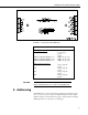
SDM-AO4 Four Channel Analog Output 4. Physical Connections Figure 1 shows the front panel of the SDM-AO4. The terminal block on the left is used for connection to the datalogger and the terminal block on the right provides the continuous analog output. The two ground ports on the left block are identical and at the same potential. Table 1 describes the terminal block connections. Multiple SDM-AO4s may be used by connecting the datalogger side of one SDM-AO4 to the next.
SDM-AO4 Four Channel Analog Output FIGURE 1. Front Panel of the SDM-AO4 TABLE 1.
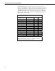
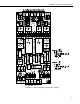
SDM-AO4 Four Channel Analog Output The SDM-AO4 has sixteen possible addresses, as shown in Table 2. The address for an SDM-AO4 is hardware selectable using jumpers at locations J12 and J8, as shown in Figure 2. The jumper at location J12 represents the least significant digit (LSD), and the jumper at location J8 is the most significant digit (MSD). The digit zero (0) is nearest the edge of the board, and the digit three (3) is the innermost jumper on the board.
SDM-AO4 Four Channel Analog Output FIGURE 2. Locational Diagram for the Address Jumpers.
SDM-AO4 Four Channel Analog Output 6. Programming NOTE This section is for users who write their own datalogger programs. A datalogger program can be generated using Campbell Scientific’s SCWIN Short Cut Program Generator. You do not need to read this section to use Short Cut. The datalogger is programmed using either CRBasic or Edlog. Dataloggers that use CRBasic include our CR800, CR850, CR1000, CR3000, and CR5000. Dataloggers that use Edlog include our CR7, CR10X, CR10, CR23X, and 21X.
SDM-AO4 Four Channel Analog Output SDMAddress: The SDMAddress parameter defines the address of the SDMAO4 to which a voltage should be applied. Valid SDM addresses are 0 through 14. Address 15 is reserved for the SDMTrigger instruction. CRBasic dataloggers use base 10 when addressing SDM devices (see Table 2). 6.1.2 SDMSpeed Instruction The SDMSpeed instruction is used to change the bit period that the datalogger uses to clock the SDM data.
SDM-AO4 Four Channel Analog Output Equation for CR5000: bit_rate=INT(k*20)*Resolution Where: k= the value entered in BitPeriod Resolution=50 nsec. 6.2 Edlog The Edlog dataloggers are programmed with the SDM-AO4 Instruction 103 (See Table 4): SDM-AO4 (P103) 1: 1 Reps 2: 00 SDM Address 3: 0000 Loc [ _________ ] The number of repetitions, Parameter 01, specifies the total number of SDMAO4 output channels to be set.
SDM-AO4 Four Channel Analog Output 6.3.1 CR5000 Program Example Although this program is for a CR5000 datalogger, programming for other CRBasic dataloggers is similar.
SDM-AO4 Four Channel Analog Output 6.3.2 CR10X Program Example Although this program is for a CR10X, programming for other Edlog dataloggers is similar. ;{CR10X} *Table 1 Program 01: 1.0000 Execution Interval (seconds) ; Code for 03001 wind measurements, WS_ms & WindDir: 1: Pulse (P3) 1: 1 2: 1 3: 21 4: 1 5: 0.75 6: 0.
SDM-AO4 Four Channel Analog Output 5: If time is (P92) 1: 0 Minutes (Seconds --) into a 2: 1 Interval (same units as above) 3: 10 Set Output Flag High (Flag 0) 6: Set Active Storage Area (P80) 1: 1 Final Storage Area 1 2: 101 Array ID ;Set array ID to 101 7: Real Time (P77) ; Output Year, Day, Hour/Minute 1: 1110 Year,Day,Hour/Minute (midnight = 0000) 8: Wind Vector (P69) ; Output Average WS, WD, StdDev WD 1: 1 Reps 2: 0 Samples per Sub-Interval 3: 0 S, theta(1), sigma(theta(1)) with polar sensor 4: 1 Wi
SDM-AO4 Four Channel Analog Output 16: Z=X+F (P34) 1: 9 X Loc [ WD_0_540 ] 2: 360 F 3: 9 Z Loc [ WD_0_540 ] ; Add 360 to the current reading ; otherwise, the current reading ; is left alone 17: End (P95) 18: End (P95) ; Scale the measurements for the SDM-AO4 to output 0 to 1000 mV 19: Z=X*F (P37) 1: 1 X Loc [ WS_ms ] 2: 20 F 3: 5 Z Loc [ WSoutput ] ; Scale WS: 0-50 mps = 0-1000 mV 20: Z=X*F (P37) 1: 9 X Loc [ WD_0_540 ] 2: 1.
Campbell Scientific Companies Campbell Scientific, Inc. (CSI) 815 West 1800 North Logan, Utah 84321 UNITED STATES www.campbellsci.com • info@campbellsci.com Campbell Scientific Africa Pty. Ltd. (CSAf) PO Box 2450 Somerset West 7129 SOUTH AFRICA www.csafrica.co.za • cleroux@csafrica.co.za Campbell Scientific Australia Pty. Ltd. (CSA) PO Box 444 Thuringowa Central QLD 4812 AUSTRALIA www.campbellsci.com.au • info@campbellsci.com.au Campbell Scientific do Brazil Ltda.