
Owner's manual
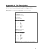


Appendix A. Pin Description
A-2
TABLE A-2. DTE 25 Pin Configuration
PIN= 25-pin number
ABR = Abbreviation for the function name
I = Signal Into the computer
O = Signal Out of the computer
PIN ABR I/O Function
1 Frame Ground.
2 TX O Transmit Data: Characters are transmitted from the
computer on this line.
3 RX I Receive Data: Characters transmitted by a peripheral
are received on this line.
4 RTS O Request To Send: The computer uses this line to
control the peripheral's PE lines.
20 DTR O Data Terminal Ready: The computer uses this line to
control the peripheral's ME and CLK/HS line.
22 RING I Ring Indicator: Raised to get the attention of the
computer.
7 SG Signal Ground: Voltages are measured relative to this
point.
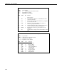
TABLE A-3. DTE 9 Pin Configuration
PIN = 9-pin number
ABR = Abbreviation for the function name
I = Signal Into the computer
O = Signal Out of the computer
PIN ABR I/O Function
1 CD I Carrier Detect
2 RX I Receive Data
3 TX O Transmit Data
4 DTR O Data Terminal Ready
5 SG Signal Ground
6 DSR I Data Set Ready
7 RTS O Request to Send
8 CTS I Clear to Send
9 RING I Ring Indicator