
User guide


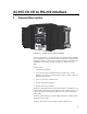

SC105 CS I/O to RS-232 Interface
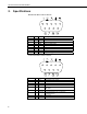
2. Specifications
RS-232 9-Pin Male Connector Pin-out:
Pin No. I/O Name Description
1 In DCD Data Carrier Detect (No Connection)
2 In RXD Received Data
3 Out TXD Transmitted Data
4 Out DTR Data Terminal Ready
5 GND Signal Ground
6 In DSR Data Set Ready (No Connection)
7 Out RTS Request to Send – Modem Enable
8 In CTS Clear to Send
9 In Ring Rings Datalogger
CS I/O 9-Pin Male Connector Pin-out:
Pin No. I/O Name Description
1 In +5 V Regulated 5 Volt supply
2 GND Ground
3 Out Ring Ring signal to datalogger
4 Out RXD SC105 transmits on this line
5 In ME Modem Enable—must be high for transfer in
ME mode
6 In SDE Synchronous Device Enable
7 In CLK/HS Clock/Handshake (for synchronous
communication)
8 +12 V Not Used
9 In TXD SC105 receives on this line
2