SC105 CS I/O to RS-232 Interface Revision: 11/13 C o p y r i g h t © 2 0 0 4 - 2 0 1 3 C a m p b e l l S c i e n t i f i c , I n c .
Warranty “PRODUCTS MANUFACTURED BY CAMPBELL SCIENTIFIC, INC. are warranted by Campbell Scientific, Inc. (“Campbell”) to be free from defects in materials and workmanship under normal use and service for twelve (12) months from date of shipment unless otherwise specified in the corresponding Campbell pricelist or product manual. Products not manufactured, but that are re-sold by Campbell, are warranted only to the limits extended by the original manufacturer.
Assistance Products may not be returned without prior authorization. The following contact information is for US and international customers residing in countries served by Campbell Scientific, Inc. directly. Affiliate companies handle repairs for customers within their territories. Please visit www.campbellsci.com to determine which Campbell Scientific company serves your country. To obtain a Returned Materials Authorization (RMA), contact CAMPBELL SCIENTIFIC, INC., phone (435) 227-9000.
Table of Contents PDF viewers: These page numbers refer to the printed version of this document. Use the PDF reader bookmarks tab for links to specific sections. 1. General Description....................................................1 2. Specifications .............................................................2 3. Set-up Menu ................................................................3 3.1 Set-up Menu Selections........................................................................4 4.
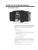
SC105 CS I/O to RS-232 Interface 1. General Description FIGURE 1-1. SC105 CS I/O to RS-232 Interface The SC105 (FIGURE 1-1) is used to interface a Campbell Scientific datalogger to any modem that is configured with an RS-232 DCE (Data Communications Equipment) serial port. The SC105 is an intelligent interface that buffers data (1 kB buffer size), allowing many RS-232 data rates, and all CS I/O port modes. Features include: • True RS-232 signal levels.
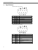
SC105 CS I/O to RS-232 Interface 2. Specifications RS-232 9-Pin Male Connector Pin-out: Pin No. 1 2 3 4 5 6 7 8 9 I/O In In Out Out In Out In In Name DCD RXD TXD DTR GND DSR RTS CTS Ring Description Data Carrier Detect (No Connection) Received Data Transmitted Data Data Terminal Ready Signal Ground Data Set Ready (No Connection) Request to Send – Modem Enable Clear to Send Rings Datalogger CS I/O 9-Pin Male Connector Pin-out: 2 Pin No.
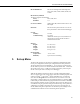
SC105 CS I/O to RS-232 Interface RS-232 Baud Rates: The SC105 will support the following baud rates: 1200, 9600, 19200, 38400, 57600, and 115200 RS-232 Parity and Data The SC105 supports the following: Parity: Even, Odd, None Data Bits: 7, 8 CS I/O Port Modes: CSDC, SDC, ME, Addressed Print Device for P96 output Electrical: The SC105 uses power from the +5 V line on the 9-pin interface connected to the datalogger Current Standby: Communicating: 3. 0.
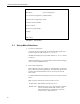
SC105 CS I/O to RS-232 Interface SC105 - SW Version 2.0 Main Menu: Current Configuration (1) CS I/O Port Configuration [Modem Enable] (2) RS-232 Port Configuration [9600] (3) Restore Factory Defaults (4) Save and Exit (5) Exit w/o Saving Settings (9) Help Enter Choice: FIGURE 3-1. Set-up Menu 3.1 Set-up Menu Selections 1) CS I/O Port Configuration An SC105 may be activated either by the Modem Enable signal or by a Synchronous Device (SDC) address (7, 8, 9, 10, or 11).
SC105 CS I/O to RS-232 Interface Additionally, there will be a ‘dead time’ after DTR is dropped of 2 seconds when data coming in on the RS232 will be ignored. For SDC Address 7, 8, 10, or 11, DTR will always be driven to +5 V. RTS will ‘key’ the data; it will be driven (+5 V) 20 ms prior to data being sent out the RS-232, and remain driven for 5 seconds after the last data is sent out the RS-232.
SC105 CS I/O to RS-232 Interface TABLE 5-1. Approximate Range, miles and km Data Rate 5.1 19 Gauge (0.9 mm) 24 Gauge (0.5 mm) 26 Gauge (0.4 mm) bps miles km miles km miles km 9,600 6.2 10.0 2.8 4.5 2.0 3.3 1,200 7.6 12.2 3.4 5.5 2.5 4.0 RAD Modem – Two Way PC SRM 4-WIRE UNCONDITIONED TELEPHONE LINE OR TWO TWISTED PAIRS SRM 9 TO 25 PIN ADAPTOR SC105 DATALOGGER FIGURE 5-1.
SC105 CS I/O to RS-232 Interface enclosures models ENC10/12, ENC12/14, or ENC16/18). Spark gap wiring is straight through such that pin to pin continuity exists between the two modems. If the modems are installed entirely within a building, the transient spark gap protection is probably not needed. FIGURE 5-2. Installation of Spark Gap Protection Occasionally, a customer needs to transmit data across longer or smaller gage wires or at higher speeds than can be done with the RAD modem powered by the SC105.
SC105 CS I/O to RS-232 Interface 5.3 Testing RAD Modem Communication The modem communication link is divided into the following three sections: 1) RAD modem computer end, 2) cable from computer modem to datalogger modem, 3) RAD modem datalogger end. When unable to establish communication with the datalogger, test each of the three sections.
SC105 CS I/O to RS-232 Interface 6. CDMA Modem Application In most modem applications, the SC105 can be used with the factory defaults. This sets the SC105 up as modem enable 9600 baud, 8 data bits, Parity None and 1 stop bit. It also sets the DTR dead time to 2 seconds. This dead time is used to prevent characters produce by the modem from waking the datalogger right after communications has been terminated. The dead time can be adjusted by changing the RS-232 DTR and RTS mode to Custom.
SC105 CS I/O to RS-232 Interface 10
Campbell Scientific Companies Campbell Scientific, Inc. (CSI) 815 West 1800 North Logan, Utah 84321 UNITED STATES www.campbellsci.com • info@campbellsci.com Campbell Scientific Africa Pty. Ltd. (CSAf) PO Box 2450 Somerset West 7129 SOUTH AFRICA www.csafrica.co.za • cleroux@csafrica.co.za Campbell Scientific Australia Pty. Ltd. (CSA) PO Box 8108 Garbutt Post Shop QLD 4814 AUSTRALIA www.campbellsci.com.au • info@campbellsci.com.au Campbell Scientific do Brasil Ltda. (CSB) Rua Apinagés, nbr.