PWC100 Present Weather Sensor Calibrator Revision: 3/12 C o p y r i g h t © 2 0 0 8 - 2 0 1 2 C a m p b e l l S c i e n t i f i c , I n c .
Warranty “PRODUCTS MANUFACTURED BY CAMPBELL SCIENTIFIC, INC. are warranted by Campbell Scientific, Inc. (“Campbell”) to be free from defects in materials and workmanship under normal use and service for twelve (12) months from date of shipment unless otherwise specified in the corresponding Campbell pricelist or product manual. Products not manufactured, but that are re-sold by Campbell, are warranted only to the limits extended by the original manufacturer.
Assistance Products may not be returned without prior authorization. The following contact information is for US and international customers residing in countries served by Campbell Scientific, Inc. directly. Affiliate companies handle repairs for customers within their territories. Please visit www.campbellsci.com to determine which Campbell Scientific company serves your country. To obtain a Returned Materials Authorization (RMA), contact CAMPBELL SCIENTIFIC, INC., phone (435) 227-9000.
PWC100 Table of Contents PDF viewers: These page numbers refer to the printed version of this document. Use the PDF reader bookmarks tab for links to specific sections. 1. Introduction..................................................................1 2. Operation and Use.......................................................1 2.1 Operating Guidelines ................................................................................1 2.2 Initial Configuration of the PWS100 for use of the Calibrator..........
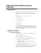
PWC100 Present Weather Sensor Calibrator 1. Introduction The PWC100 is a customer field calibration validation device for the PWS100. The PWC100 calibrator system simulates particle and visibility data for the PWS100 allowing verification of the calibration constants held within the system.
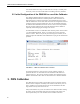
PWC100 Present Weather Sensor Calibrator Care must be taken not to drop or scratch either the velocity or visibility units as this may cause errors that could result in tests failing when they shouldn’t. 2.2 Initial Configuration of the PWS100 for use of the Calibrator The visibility calibration disks provided as part of the calibration kit are individually calibrated and have a number printed on them to indicate the measured signal in a reference instrument.
PWC100 Present Weather Sensor Calibrator 3.1 Installing and Connecting up the Calibrator • Remove the existing plastic blanking screws from their positions on the PWS center block. • Fix the PWC100 visibility calibrator unit to the center position on the PWS using two of the metal countersunk fixing screws provided. (Connector for the calibrator) FIGURE 3-1.
PWC100 Present Weather Sensor Calibrator 3.2 Starting the Tests All PWC100 tests can be performed without the need to access the PWS with a PC. Only once the tests are finished and if changes to the calibration constants are needed, will a PC be required to change the system configuration. If at any point the LEDs behave unexpectedly, check the status table at the end of this section.
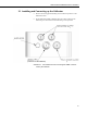
PWC100 Present Weather Sensor Calibrator Step 2: Performing the visibility maximum limit check • Remove the PWC100 visibility calibration disk and place it back into its box. • Place blanking plug into upper sensor head as shown in diagram above. • At this point, LED L and LED C should be flashing slowly. • Once you are ready, press START. • LED L and LED C will be illuminated for the duration of the test. This test will take approximately two minutes.
PWC100 Present Weather Sensor Calibrator Step 3: Position 1: Center position Attaching the velocity calibration unit 6 • Fix the PWC100 velocity calibrator unit to the center position on the PWS using two of the countersunk fixing screws provided • Check that the velocity calibrator is located correctly and securely. • LED C should now be flashing slowly and all other LEDs should be off. • Once you are ready, press START. • The test is now automated and the disk should start rotating.
PWC100 Present Weather Sensor Calibrator Step 4: Position 2: Left • Move the calibrator into the left hand position by unscrewing the calibrator mounting screws slightly and sliding the calibrator fully to the left. Then retighten the screws once in position. • Visually check that the calibrator is located correctly and securely. • LED L should now be flashing slowly and all other LEDs should be off. • Once you are ready, press START. • The test is now automated and the disk should start rotating.
PWC100 Present Weather Sensor Calibrator Step 5: Position 3: Right • Move the calibrator into the right-hand position by unscrewing the calibrator mounting screws slightly and sliding the calibrator fully to the right. Then retighten the screws once in position. • Visually check that the calibrator is located correctly and securely. • LED R should now be flashing slowly and all other LEDs should be off. • Once you are ready, press START.
PWC100 Present Weather Sensor Calibrator Step 6: Final stage • Remember to reinstall the plastic blanking screws back into the PWS100 before leaving the site. • If a CS215-PWS or other piece of equipment was unplugged in order to perform the tests, then ensure it is reconnected. • Remember to check that the blanking plug has not been left in the PWS. • Place all calibration equipment carefully back into its correct box being careful not to scratch the visibility disk.
PWC100 Present Weather Sensor Calibrator Quick look LED status table Ready/complete state Test state Left Visibility test Flash Visibility maximum range test Flash Velocity test position 1 (Center) Velocity test position 2 (Left) Center Right Flash Flash Running state Left Center ON ON Flash Right ON ON ON Flash ON Velocity test position 3 (Right) Flash ON Final result states Calibration passed ON ON ON Calibration required Flash Flash Flash Flash Flash Error conditions Fault
PWC100 Present Weather Sensor Calibrator It is also recommended that the operator stands behind the laser hood while the PWS is active. 6. Electrical Parameters 6.1 PWC100 Voltages and Currents Nominal Max Notes General details Standby current 29 mA 30 mA No tests running Operating current 125 mA 150 mA Disk rotating at test speed Spin up current 500 mA 700 mA Disk spinning up to speed +12 V +2 8V Main supply voltage + Volts 6.
PWC100 Present Weather Sensor Calibrator 12
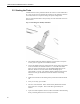
Appendix A. Assembly Guidelines A.1 Assembly Guidelines The PWC100 visibility and velocity calibration disks can easily be removed for cleaning or repair if needed. FIGURE A-1. Attaching the velocity disk FIGURE A-2.
Appendix A. Assembly Guidelines FIGURE A-3. Attachment of the velocity calibrator A.
Campbell Scientific Companies Campbell Scientific, Inc. (CSI) 815 West 1800 North Logan, Utah 84321 UNITED STATES www.campbellsci.com • info@campbellsci.com Campbell Scientific Africa Pty. Ltd. (CSAf) PO Box 2450 Somerset West 7129 SOUTH AFRICA www.csafrica.co.za • cleroux@csafrica.co.za Campbell Scientific Australia Pty. Ltd. (CSA) PO Box 8108 Garbutt Post Shop QLD 4814 AUSTRALIA www.campbellsci.com.au • info@campbellsci.com.au Campbell Scientific do Brazil Ltda.