PVS4100/4120/4150 Portable Samplers Revision: 4/12 C o p y r i g h t © 2 0 1 1 - 2 0 1 2 C a m p b e l l S c i e n t i f i c , I n c .
Warranty The PVS4100/4120/4150 Portable Samplers are warranted for thirty-six (36) months subject to this limited warranty: “PRODUCTS MANUFACTURED BY CAMPBELL SCIENTIFIC, INC. are warranted by Campbell Scientific, Inc. (“Campbell”) to be free from defects in materials and workmanship under normal use and service for twelve (12) months from date of shipment unless otherwise specified in the corresponding Campbell pricelist or product manual.
Assistance Products may not be returned without prior authorization. The following contact information is for US and international customers residing in countries served by Campbell Scientific, Inc. directly. Affiliate companies handle repairs for customers within their territories. Please visit www.campbellsci.com to determine which Campbell Scientific company serves your country. To obtain a Returned Materials Authorization (RMA), contact CAMPBELL SCIENTIFIC, INC., phone (435) 227-9000.
PVS4100/4120/4150 Table of Contents PDF viewers: These page numbers refer to the printed version of this document. Use the PDF reader bookmarks tab for links to specific sections. 1. Product Overview......................................................1-1 1.1 1.2 Introduction........................................................................................ 1-1 Features .............................................................................................. 1-2 1.2.
PVS4100/4120/4150 Table of Contents 4. Maintenance.............................................................. 4-1 4.1 4.2 General Maintenance.......................................................................... 4-1 Testing System Vacuum..................................................................... 4-1 5. Programming ............................................................ 5-1 5.1 5.2 5.3 5.4 5.5 5.6 5.7 General Programming ........................................................
PVS4100/4120/4150 Table of Contents Appendices A. Principles of Operation........................................... A-1 B. Parts List.................................................................. B-1 C. Programming 4-20mA for Flow Proportional Sampling ............................................................... C-1 List of Figures 1-1. 1-2. 1-3. 2-1. 2-2. 3-1. Highlights of the PVS4100 and PVS4120 Samplers ........................... 1-2 Highlights of the PVS4150 Sampler..........................
PVS4100/4120/4150 Table of Contents iv
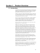
Section 1. Product Overview 1.1 Introduction The PVS4100, PVS4120 and PVS4150 Portable Samplers are automatic liquid samplers for water and wastewater applications. PVS Samplers are capable of gathering fluid automatically from a variety of sources, including containers, open channels, sewers, pipes, and any open source of water. Samplers are designed for reliable unattended sample collection. Portable units are capable of keeping the temperature of the deposited liquid at 4ºC (39.
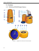
Section 1. Product Overview 1.2 Features 1.2.1 PVS4100 and PVS4120 Sampler Features 1 7 8 2 9 10 3 31.875” (810 mm) 4 11 12 5 6 13 14 Diameter 16.375” (416 mm) 15 16 17 18 19 20 FIGURE 1-1.
Section 1. Product Overview TABLE 1-1. PVS4100 and PVS4120 Sampler Features Number 1 2 Item Top Handle Enclosure 3 Intake Hose Slot 4 Clasps 5 Signal Panel 6 7 Folding Handles Intake Hose Connection 8 Wiring 9 Nuts to adjust volume 10 Metering Chamber 11 Battery 12 13 Multi-Function Input Controller Sinker. Optional Strainer.
Section 1. Product Overview 1.2.2 PVS4150 Sampler Features 1 2 10 3 11 4 12 13 5 6 7 14 8 15 9 16 17 14.40” (366 mm) 18 24.60” (625 mm) 19 19.70” (500 mm) FIGURE 1-2.
Section 1. Product Overview TABLE 1-2. PVS4150 Sampler Features Number Item Description 1 Signal Panel Green Light: Integral Battery Charging (AC power connected) Red Light: External Battery Reverse Polarity Toggle Switch: Power On/Off Plug: AC power (coupled with optional signal cable when supplied). 2 Volume Control Tube This stainless steel tube is raised or lowered manually using the fitting to set the sample volume (see FIGURE 1-3 on page 1-6).
Section 1. Product Overview 1.2.3 Sampler Vacuum System Features FIGURE 1-3.
Section 1. Product Overview TABLE 1-3. Vacuum System Features Number Item Description 1 Solenoid Valves Control the air flow from pump to sampler, either purging or sucking. 2 Pump Located behind a sheet of metal, the pump does not come into contact with any liquid whatsoever. It does all the drawing and purging through using a vacuum and compressor. 3 Touchpad Controller Controls sampler program and offers status feedback on LCD.
Section 1. Product Overview 1.2.4 Signal Panel PVS4100 and PVS4120 Red Light: Reverse Polarity, Green Light: Power Left Plug: External Signals (to be used with optional signal cable) Right Plug: Power – 120VAC or 12VDC Left Fuse: 120VAC, Right Fuse: 12VDC Toggle Switch: Power On/Off PVS4150 Green Light: Integral Battery Charging (AC power connected) Red Light: External Battery Reverse Polarity Toggle Switch: Power On/Off Plug: AC power (coupled with optional signal cable when supplied).
Section 1. Product Overview 1.3 Specifications 1.3.1 PVS4100 Portable Sampler Specifications TABLE 1-4. PVS4100 Sampler Specifications Dimensions Height: 809 mm (31.875 in) Diameter: 428 mm (16.85 in) Extended Base: Height: 962 mm (37.875 in) Diameter: 428 mm (16.85 in) Weight (without battery) 11.8 kg (26 lbs) Enclosure Molded medium density linear polyethylene, 3 piece construction, all SS fittings. Protection Rating: IP 55, Dust protection, water jets. Power Requirements Sampler: DC Output: 13.
Section 1. Product Overview 1.3.2 PVS4120 Lightweight Portable Sampler Specifications TABLE 1-5. PVS4120 Sampler Specifications Dimensions Height: 31.875 in (809 mm) Diameter: 16.85 in (428 mm) Extended Base: Height: 37.875 in (962 mm) Diameter: 16.85 in (428 mm) Weight (without battery) 10.4 kg [23 lbs] Enclosure Molded medium density linear polyethylene, 3 piece construction, all SS fittings. Protection Rating: IP 55, Dust protection, water jets.
Section 1. Product Overview 1.3.3 PVS4150 Ultra-Portable Sampler Specifications TABLE 1-6. PVS4150 Sampler Specifications Dimensions H: 24.6” x W: 19.7” x D: 14.4” [H: 625mm x W: 500mm x D: 366mm] Weight (without battery) 35.5 lbs [16.1 kg] Enclosure HPX high performance resin. Press & Pull latches, and soft-grip handles. Protection Rating: IP 67, Dust-tight, water-tight (depending on options chosen). Power Requirements Integral Battery: 12 VDC, 7 AH, 4 lbs.
Section 1. Product Overview 1.3.4 Controller Specifications TABLE 1-7.
Section 1. Product Overview 1.3.5 Vacuum System Specifications TABLE 1-8. Vacuum System Specifications Feature Description Switches Run/Off (SPST Toggle). Sample Volume Adjustable, 50cc to 500cc [PVS4100 and PVS4120] Adjustable, 50cc to 250cc [PVS4150] Sample Transport Velocity PVS4100: Minimum of 3 ft/sec at 20 ft of lift (3/8” ID intake line). PVS4100: Minimum of 3 ft/sec at 16 ft of lift (5/8” ID intake line). PVS4100: Maximum Vertical 27.5 ft.
Section 1. Product Overview 1.3.6 Sample Container Options TABLE 1-9. Sample Container Options – PVS4100 and PVS4120 Feature Description Composite (single) containers 9 liter (2.3 US Gal) high density polyethylene (HDPE) 9 liter (2.3 US Gal) polypropylene (PP) 10 liter (2.5 US Gal) Glass [with extended base] Discrete (multiple) containers 500cc (0.5 L) Wedges (PP) [24 bottles] 500cc (0.
Section 1. Product Overview Composite Sampling is for drawing water samples into one large container. This is the simplest way of taking samples and typical for most situations where a sampler is set up to measure effluent in one location. It is also significantly less expensive than discrete sampling. 1.3.8 Sample Transport Velocity TABLE 1-11. Vertical Velocity 0’ 5’ 10’ 15’ 18’ 20’ 22’ 25’ 27’ 28’ Height 3/8” ID Large pump (BVS 4300, CVS 4200, PVS4100) 7.1 7.1 6.0 5 4.4 4.1 3.6 3 2.
Section 1. Product Overview TABLE 1-12. Horizontal Velocity 25’ 50’ 75’ 100’ 175’ 200’ 250’ Distance 3/8” ID Large pump (BVS 4300, CVS 4200, PVS4100) 7.1 6.2 5.6 5.0 4.0 3.7 2.6 Ft/sec 3/8" ID Small pump (PVS4120, PVS4150) 5.1 4.7 4.2 4.1 3.4 3.1 2.3 5/8" ID Large pump 5.0 4.7 4.3 4.2 3.7 3.3 2.4 1.3.8.
Section 1. Product Overview detailed information for your specific application, please contact a Campbell Scientific applications engineer. 1.3.9 Special Systems 1.3.9.1 5/8 Systems In applications with large particles or materials in the source liquid, a 5/8” ID system will help prevent clogging. The added diameter adds 66% more volume to the entire system. As of 2010, both composite and discrete samplers are available in 5/8”.
Section 1. Product Overview 1.4 Portable Sampler Model Selection Guide PVS Samplers come in a variety of models designed for variations in weight, pump strength, battery, larger intake hose (5/8” ID), ease-of-transport, fitting in manholes, discrete or composite sampling, protection rating for dust and water, signal options, and budgets.
Section 2. Installation 2.1 Cabinet Positioning Place the sampler on a level surface as close as practical to the sample source. Refer to the speed charts for maximum expected lift and draw. Manhole installation may require 3-point suspension harness. Sampler must be located above sample source, or liquid will flood the machine. For situations where this is not possible, please contact a Campbell Scientific application engineer for solutions on pressurized sources. FIGURE 2-1.
Section 2. Installation 2.2 Intake Hose Ensure the intake hose is submerged at all times throughout different flow velocities. CAUTION Twenty-five feet of intake hose is provided with the sampler. Shortening the hose is not recommended since this length of hose provides sufficient back pressure to the metering chamber, allowing the pump to efficiently expel all solids into the sampler container. Coil any excess intake hose in a manner to provide natural drainage away from the sampler.
Section 2. Installation 2.5 Signal Wiring External input capabilities of the sampler are implemented by the use of an optional external signal cable plugged into an external receptacle on the side of the sampler. External inputs of different types can be used by choosing the appropriate pair of wires in the cable. On the PVS4150 the signal cable is combined with the AC Power cable, thus limiting the number of connections possible. FIGURE 2-2.
Section 2. Installation 2.6 Installation Checklist Check the following items prior to use of sampler: 1) Sampler is mounted securely and level. 2) Intake Hose: - Free of kinks. - Properly installed into liquid. - Properly connected to volume control tube on metering chamber. 3) Discharge hose: - Free of kinks. - Natural downward slope to sample container. - Properly connected to (or in) sample container. 4) Power requirements: - Check battery electrical condition. - Recharge if necessary.
Section 3. Operation 3.1 Operating Sequence 3.1.1 Sampling Sequence SAMPLING PROCESS: 1. High pressure air purge of intake hose. 2. Liquid is drawn into the metering chamber, up to the liquid sensing rod. 3. All excess liquid is purged from the system down to the level set by the volume control tube. 4. The sample is then released into either one composite container or one of several discrete containers.
Section 3. Operation Should the sampler, for any reason, not be able to draw a sufficient volume of fluid to obtain a sample, the unit automatically initiates a second attempt. Should a sample still not be delivered, the sequence will be abandoned and the unit will await the next initiation. Upon two consecutive failures, the sampler will suspend the sampling program until manually RESTARTed.
Section 3. Operation IMPORTANT The volume control tube should always be located below the liquid sensing rod. NOTE Hold the bottom nut while loosening / tightening the top nut, or it may become loosened from the metering chamber cover and create an imperceptible leak in the vacuum system. 3.2.2 Liquid Sensing Rod This probe, also called the “level control rod”, is used to stop the sample intake. Always ensure that its lower end is located above the volume control tube.
Section 3. Operation 3.3 Battery 3.3.1 Battery: Operating and Backup (optional) CHARGING AND REVERSE POLARITY PROTECTION The sampler will charge ONLY the factory installed internal battery. This charging takes place continually as long as there is incoming line power. Should the need arise to only charge the internal battery, as would be required to store the sampler for an extended period of time, simply place the “ RUN / OFF “ toggle switch in the OFF position, and leave the sampler power breaker on.
Section 3. Operation 3.3.2 Battery: Microprocessor SAMPLER CONTROLLER BACKUP BATTERY The controller contains a 1/2AA, 3.6V lithium backup battery to maintain user settings during loss of system power. If power is removed for any reason, the controller will start a planned shutdown procedure which will save all user settings while its operating voltage is reduced from 5V to approximately 3.3V. The rate at which this voltage drops is slowed by the presence of a supercapacitor.
Section 3. Operation 3.4 Test Procedure 1. Set volume control tube to 200 cc. 2. Set level probe 1” above bottom of volume control tube. 3. Turn on power. Place the “RUN/OFF” switch in the “RUN” position. After an initial delay of 15 to 20 seconds, the display will show a two line message, the top line displaying SAMPLER HALTED and an alternating message on the second line displaying why the sampling procedure was interrupted as well as the event time and date. 4.
Section 3. Operation SAMPLER WILL NOT TAKE TIMED SAMPLE: a) Sampler controller defective. SAMPLER WILL NOT INITIATE FROM AN EXTERNAL CONTACT: Check wiring from terminal strip to sampler controller plug. (Terminals 12 & 13) a) Sampler controller is defective. b) Sampler controller not programmed for External Contact input. PUMP IS OPERATING, NO AIR PURGE OF INTAKE LINE: Check for blockage of intake hose by removing hose from the metering chamber volume control tube.
Section 3.
Section 4. Maintenance The following maintenance procedure should be performed at regular intervals: 4.1 General Maintenance 1. Disconnect power. 2. Open metering chamber by removing wing nuts and chamber cover. 3. Clean volume control tube and level sensing probe with mild detergent. Alternatively, exchange tube and probe with clean set. Do not use any cleaner which may be harmful to the metering chamber cover. Do not use solvents such as acetone, benzene, carbon tetrachloride or lacquer thinners.
Section 4. Maintenance 5. 4-2 If still system is still not performing at its peak, inspect pump and all pump tubing.
Section 5. Programming 5.1 General Programming 5.1.1 Guidelines Controller settings may be changed at any time. Changes are termed NEW ENTRIES. No NEW ENTRIES will be acted upon unless the controller is RESTARTed. Once RESTARTed, all NEW ENTRIES become ACTIVE SETTINGS. Every time the controller is RESTARTed, all accumulators (i.e. SAMPLES TAKEN, TIME REMAINING, REMAINING PULSES, etc.) are cleared and the ACTIVE SETTINGS are reloaded unless NEW ENTRIES have been made.
Section 5. Programming 5.1.2 Touchpad Keys TABLE 5-1. Touchpad Button Descriptions Button Description The VIEW key is used to review alterable parameters currently in use. It has no effect on the program being executed at the time. Once pressed, the user is prompted for a FUNCTION to be viewed. The parameters visible under the function can be stepped through using the ENTER key. The SET key is used to change program settings or the entire sampling program.
Section 5. Programming TABLE 5-1. Touchpad Button Descriptions Button Description The RESTART key is used to load any new parameters into the operating program. Pressing it twice will initialize the program and terminate any existing sample program. Any parameters altered under the SET command are updated to the active program. If no parameters have been changed, the program is reset to its first instruction and the same sampler program is started again.
Section 5. Programming TABLE 5-1. Touchpad Button Descriptions Button Description MANUAL PURGE. Purges the intake line independent of program control, as long as a programmed cycle has not started. Sampler starts its pump, creating pressure in the sample intake tube to purge it of any excess material that may be present. Button must be pressed twice to purge line. Sustained pressure on the key during the second press will cause purging to continue until the key is released. MANUAL ADVANCE.
Section 5. Programming will begin again. There is no loss of count the sample cycle. Pulse requirements of the system are detailed in the specifications. 4-20mA INPUT Where external devices do not themselves generate pulses in any relation to their process but generate a current signal of 4-20 mA, this input option will generate internal pulses proportional to the incoming 4-20 mA signal.
Section 5. Programming DAILY CYCLE Allows the sampler to deposit equal sample volumes into a predetermined number of containers per programmed day. Each day may have any number of samples taken, dependent on the SAMPLE INITIATION mode chosen. Deposits are made to as many as 9 containers per day, to a cumulative total of 24 containers. (e.g.
Section 5. Programming SAMPLE INITIATION (parameters for frequency of samples). Select, using arrows, which parameter you would like, and adjust settings (see 5.4 Programming Sample Initiation). Options: DISABLE; INTERVAL TIME; PULSE INPUT; 420mA INPUT; EXTERNAL CONTACT. Press “ENTER” twice. PROGRAM TYPE (which type of sampling program). Select, using arrows, which parameter you would like, and adjust settings (see 5.5 Programming Program Type).
Section 5. Programming 5.2.4 Setting Program Parameters Individually To modify any of the settings individually press the “SET” button followed by the appropriate button based on what parameter is being changed. 5.3 Programming START DELAY 5.3.1 START DELAY Overview START DELAY is the function which will delay the beginning of a sample program until certain external conditions are met.
Section 5. Programming The sampler controller can react to an external dry contact, otherwise known as a zero-voltage contact, to activate a sample program on demand. This will generally be when external conditions have caused a relay to close, requiring a sample program be started at that time. This option is a special case of the external contact option. The key difference is that the contact closure must be present for a pre-programmed time, thus enabling verification of the signal.
Section 5. Programming When setting the time, a single flashing digit indicates an input from a numeric key is required. Press a number key to enter a value. The next digits flash in succession. Enter each as required. The format is HH:MM. When the four digits are entered, press ENTER. Any wrong entries will require reentry. There are two methods of correcting a mistake. The digit flashing “wraps around” and begins again, at which time the correct entry may be pressed.
Section 5. Programming 5.3.3 START DELAY using Pulse Input The following sequence of entries are made on the Touchpad to create a future starting time for the operation of the Sampler. The ACTIVE SETTINGS are not being altered. 1. Press the SET key. 2. Press the START DELAY key. 3. Press an ARROW key. Continue until Pulse Input is shown on the display. 4. Press the ENTER key.
Section 5. Programming The controller has now been given a new value for START DELAY. The new values reside in the NEW ENTRIES area of the controller memory. To make these changes active, press the RESTART key, then again press it to confirm your choice. The controller will then wait until the required pulses have been received before starting its sampling program. Summary of Sequence: SET, START DELAY, ARROW(S), ENTER, #######, ENTER, RESTART, RESTART. 5.3.
Section 5. Programming The display will show a new screen containing the option title 4-20mA INPUT on the top line and a 7 digit number with the leftmost digit flashing as a prompt for input. The 4-20 mA input will be converted by the controller to pulses, proportional to the span of the input, at the rate set in the specifications. To set the number of pulses required to be input before a sample program is started, use the ARROW keys to move the flashing prompt until it is over the digit requiring change.
Section 5. Programming 5.3.5 START DELAY using External Contact The following sequence of entries are made on the Touchpad to create a future starting time for the operation of the Sampler. The ACTIVE SETTINGS are not being altered. 1. Press the SET key. 2. Press the START DELAY key. 3. Press an ARROW key. Continue until External Contact is shown on the display. 4. Press the ENTER key. The display will echo the last entry with . The controller has now been given a new value for START DELAY.
Section 5. Programming 5.3.6 START DELAY using Level Control The following sequence of entries are made on the Touchpad to create a future starting time for the operation of the Sampler. The ACTIVE SETTINGS are not being altered. 1. Press the SET key. 2. Press the START DELAY key. 3. Press an ARROW key. Continue until Level Control is shown on the display. 4. Press the ENTER key. The display will change to read “Minimum Contact Time: 01 seconds”. The actual time shown may be any two digit number.
Section 5. Programming The controller has now been given a new value for START DELAY. The new values reside in the NEW ENTRIES area of the controller memory. To make these changes active, press the RESTART key, then again press it to confirm your choice. The controller will then wait until it receives a contact closure (at the External Start inputs on the terminal block). The contact must remain closed for the length of time programmed in the steps above.
Section 5. Programming This option will allow the controller to determine the SAMPLE INITIATION based on external pulses. Pulses fed to an internal accumulator in the controller will be compared to the setting entered by the operator and will cause a sample cycle to start. The accumulator will reset immediately and counting of pulses will begin again. There is no loss of count during the sample cycle. Pulse requirements of the system are detailed in the specifications.
Section 5. Programming 3. Press an ARROW key. Continue until Interval Time is shown on the display. 4. Press the ENTER key. When setting the time, a flashing digit prompts for input from a numeric key. To set the time, press a numeric key to enter a value and advance to each digit in succession. The format is HHH:MM. The minimum time can be set to 1 minute, however, practical considerations, such as equipment duty cycle, maintenance and service life suggest times of 3 minutes or longer.
Section 5. Programming 5.4.3 SAMPLE INITIATION using Pulse Input The following sequence of entries are made on the Touchpad to form a basic operating parameter for operation of the sampler. This will determine the number of pulses from the start of a sample cycle to the start of the next sample cycle. The ACTIVE SETTINGS are not being altered. 1. Press the SET key. 2. Press the SAMPLE INITIATION key. 3. Press an ARROW key. Continue until Pulse Input is shown on the display. 4. Press the ENTER key.
Section 5. Programming The controller has now been given a new value for SAMPLE INITIATION. The new values reside in the NEW ENTRIES area of the controller memory. To make these changes active, press the RESTART key, then again press it to confirm your choice. The controller will then wait until the required pulses have been received before taking a sample. Summary of Sequence: SET, SAMPLE INITIATION, ARROW(S), ENTER, #######, ENTER, RESTART, RESTART. 5.4.
Section 5. Programming The display will show a new screen containing the option title 4-20mA INPUT on the top line and a 7 digit number with the leftmost digit flashing as a prompt for input. The 4-20 mA input will be converted by the controller to pulses, proportional to the span of the input, at the rate set in the specifications. To set the number of pulses required to be input before a sample is taken, use the ARROW keys to move the flashing prompt until it is over the digit requiring change.
Section 5. Programming 5.4.5 SAMPLE INITIATION using External Contact The following sequence of entries are made on the Touchpad to form a basic operating parameter for operation of the sampler. This will determine the time between samples being taken. The ACTIVE SETTINGS are not being altered. 1. Press the SET key. 2. Press the SAMPLE INITIATION key. 3. Press an ARROW key. Continue until External Contact is shown on the display. 4. Press the ENTER key.
Section 5. Programming 5.5 Programming PROGRAM TYPE 5.5.1 PROGRAM TYPE Overview PROGRAM TYPE is the function which determines how the sampler will perform its program. A variety of options are available. These options are programmable from the Touchpad and require only that the sampler have the correct equipment configuration to utilize them. The basic function of the Program Type is to determine the movement of the distributor.
Section 5. Programming This option will cause the sampler to step to a new container regardless of the status of the SAMPLE INITIATION setting. For example, the actual sampling may be under the control of a flowmeter and taking samples based on the flow rate as determined by pulses or 4-20mA input to the controller. When the user-programmed timed interval has elapsed, the controller will step to a new container. The Timed Step can be set for any interval up to 99 hours 59 minutes.
Section 5. Programming The display will respond with the message “Terminate After 0000009 Samples”. The numerical value will be whatever value was last placed in the controller’s memory, usually after previous programming. To keep the previous value press ENTER, or, to set a new value, use the ARROW keys to advance the flashing prompt to the desired location and replace the digits under the prompt by using the digits (0-9) on the Touchpad.
Section 5. Programming 5.5.3 PROGRAM TYPE - Daily Cycle The following sequence of entries are made on the Touchpad to describe how the Sampler controller is to store the samples it takes, in the hardware specified in its configuration. The ACTIVE SETTINGS are not being altered. 1. Press the SET key. 2. Press the PROGRAM TYPE key. 3. Press an ARROW key. Continue until Daily Cycle is shown on the display (for storage in a single container or a multiple container array). 4. Press the ENTER key.
Section 5. Programming can be chosen. If no change in the displayed value is required, the value has been changed or the value is zero, pressing ENTER will advance the day of the week. Therefore... Press ENTER. Repeat the above procedures until all the required containers, on their respective days, have been allocated, or the 7 days of the week are all selected.
Section 5. Programming 1. Press the SET key. 2. Press the PROGRAM TYPE key. 3. Press an ARROW key. Continue until Daily Cycle is shown on the display. 4. Press the ENTER key. The display will show the response “DAILY CYCLE Total Bottles nn“. The two digits, nn, will flash, indicating they can be changed . In this application, the number of bottles must be set to 24. Press ENTER. The second line of the display will change to show a day of the week.
Section 5. Programming The display will echo the last entry with PROGRAM TYPE . The controller has now been given a new value for PROGRAM TYPE. The new value resides in the NEW ENTRIES area of the controller memory. To make these changes active, press the RESTART key, then again press it to confirm your choice. The controller will then be set to perform as a Dual Station Sampler in conjunction with the parameters programmed under the START DELAY and SAMPLE INITIATION variables.
Section 5. Programming The display will show the response “CONSECUTIVE Total Bottles nn“. The two digits, nn, will be flashing, indicating they can be changed by scrolling with the arrow keys. Press ENTER. The display now reads “nn bottles per Sample Cycle”. A previously set value will be displayed. One of the digits is flashing. Using the number keys (0-9), enter the first digit of the number of bottles that will be used at each sampling time determined by the programming setting, i.e.
Section 5. Programming 5.5.6 PROGRAM TYPE - Multi-Composite The following sequence of entries are made on the Touchpad to describe how the Sampler controller is to store the samples it takes, in the hardware specified in its configuration. The ACTIVE SETTINGS are not being altered. 1. Press the SET key. 2. Press the PROGRAM TYPE key. 3. Press an ARROW key. Continue until Multi-Composite is shown on the display (for storage in multiple container array). 4. Press the ENTER key.
Section 5. Programming Press ENTER. The display now reads PROGRAM TYPE . The controller has now been given a new value for PROGRAM TYPE. The new value resides in the NEW ENTRIES area of the controller memory. To make these changes active, press the RESTART key, then again press it to confirm your choice. The controller will then be set to perform as a Multi-Composite Sampler in conjunction with the parameters programmed under the START DELAY and SAMPLE INITIATION variables.
Section 5. Programming 4. Press the ENTER key. Press ENTER. The display will show the response “TIMED STEP Total Bottles nn”. The two digits, nn, will be flashing, indicating they can be changed by scrolling with the arrow keys. Press ENTER. The bottom line of the display now reads “Step Intvl 00:00”. A previously set value is displayed. One of the digits is flashing, prompting for first digit of a numeric input. The format is HH:MM.
Section 5. Programming 5.6 Programming OTHER OPTIONS 5.6.1 OTHER OPTIONS Overview SET or VIEW This feature allows the user to SET or VIEW the internal Real-Time clock of the microprocessor. This feature allows the user to SET or VIEW the duration for which the sampler will purge the intake line prior to drawing in a sample to the chamber. The maximum allowable setting is 99 seconds. This feature allows the user to change how the pinch valve will operate during sampling cycles.
Section 5. Programming attempts being made to obtain the failed sample, will wait until the next sample initiation. VIEW ONLY The controller will remember conditions encountered during normal operation. Reasons for premature ending of a set program will also be saved in memory. By VIEWing this feature, this information can be obtained at the time the sampler is checked. Values retained by the controller to indicate number of missed samples.
Section 5. Programming 5.6.2 OTHER OPTIONS - Clock The following sequence of entries are made on the Touchpad to alter the Real Time Clock, running internally in the controller, which is the basis for all timed functions. The ACTIVE SETTINGS are not being altered and there are no NEW ENTRIES generated. 1. Press the SET key. 2. Press the OTHER OPTIONS key. 3. Press an ARROW key. Continue until Clock is shown on the display (for updating the internal Real Time Clock). 4. Press the ENTER key.
Section 5. Programming Press ENTER. The bottom line of the display shows a date in the format DD-MM-YY. The DD pair is a pair of digits with the normal range of 00 - 31. Set by number keys (0-9) individually. Press ENTER. The MM characters are set using the ARROW keys for the choice of one regular calendar month. Press ENTER. The YY pair of digits are set using the number keys again, corresponding to the last two digits in the year. Set each digit individually. Press ENTER.
Section 5. Programming 2. Press the OTHER OPTIONS key. 3. Press an ARROW key. Continue until Purge Time is shown on the display (for operating time when the sampler is in the purge mode of the Sample cycle, pressurizing the inlet hose to clear it of obstructions and fluid). 4. Press the ENTER key. The display shows the response “PURGE TIME SS seconds”. The first digit of SS is flashing. A previously set value may be displayed.
Section 5. Programming 5.6.4 OTHER OPTIONS - Pinch Valve The following sequence of entries are made on the Touchpad to describe how the Sampler controller is to operate some of the hardware specified in its configuration. The ACTIVE SETTINGS are not being altered. 1. Press the SET key. 2. Press the OTHER OPTIONS key. 3. Press an ARROW key. Continue until Pinch Valve is shown on the display. 4. Press the ENTER key.
Section 5. Programming The controller has now been given a new value for PINCH VALVE. The new value resides in the NEW ENTRIES area of the controller memory. To make these changes active, press the RESTART key, then again press it to confirm your choice. The controller will then be set to perform in conjunction with the parameters programmed under the START DELAY, SAMPLE INITIATION and PROGRAM TYPE settings. Summary of Sequence: SET, OTHER OPTIONS, ARROW(S), ENTER, ARROW(S), ENTER, RESTART, RESTART. 5.6.
Section 5. Programming The display will show the response “FAULT SHUTDOWN Enabled / Disabled”. All the characters on the bottom line are flashing, therefore the choice is made with the ARROW keys. The choice is a toggle between ‘Enabled’ or ‘Disabled’. If disabled, the controller will make a lengthy attempt to obtain a sample, then return control to the SAMPLE INITIATION to try again. The controller will accumulate a count of unsuccessful (abandoned) attempts. Press ENTER.
Section 5. Programming 5.7 Viewing Information 5.7.1 Viewing Programmed Information To see current settings, press the VIEW button, followed by the appropriate button as described on its label. The display will show current parameter settings, beginning with the requested major category. Press the ENTER key. If more information is available for a given parameter, it will be displayed. Continue pressing ENTER until no new information is presented. The display will “wrap-around” to its first message.
Section 5. Programming OTHER OPTIONS Press the VIEW key. Press the OTHER OPTIONS key. Use ARROW keys to navigate to desired option on the flashing display. Press ENTER to view. Available options are: Clock - Time, Date (including Day) Purge Time - Time in seconds Pinch Valve - Normally Open or Closed Fault Shutdown - Enabled or Disabled Sampler Status - Error and system messages that have been lost from the display by keyboard entry.
Section 5. Programming NEW ENTRIES Press the VIEW key. Press the NEW ENTRIES key. If no “NEW ENTRIES” have been made, the display will show “No New Entries View Active Set”. If new parameters have been set, but the unit hasn’t been RESTARTed, the display will show “NEW ENTRIES ‘ENTER’ to list”. Press the ENTER key. The display will show the START DELAY programming.
Section 5. Programming REMAINING TIME Press the VIEW key. Press the REMAINING TIME key. The display will show various time counters dependent on the programming of the START DELAY and SAMPLE INITIATION parameters. Priority goes to START DELAY, which will show an incrementing time for event related delays or decrementing time for time related delays. The display will then yield to SAMPLE INITIATION for an elapsed time display for event related inputs and Remaining Time display for time related inputs.
Section 5.
Appendix A. Principles of Operation Switching Methods (Sinking / NPN) LOAD Sensor Sinking (NPN) Switch The Sinking method connects or switches one side of the load to the negative (-) side of the power supply. The positive (+) side is connected directly to the other side of the load as shown. “NPN” refers to the type of transistor used to act as a switch in this type of solid-state sensor.
Appendix A.
Appendix B. Parts List This is a partial list of most frequently requested PVS Sampler replacement parts. TABLE B-1. PVS Replacement Parts Part No. Old Part No. (Prior to 8-1-11) Description SAMPLE CONTAINERS 27952 27-01-01 500cc Wedge (Polypropylene) 27953 27-01-02 1000cc Wedge (Polypropylene) 26897 27-03-05 2.3 Gallon (9L) Nalgene with side plug (Polyethylene) 28258 27-03-05P 2.3 Gallon (9L) Nalgene with side plug (Polypropylene) 27-03-05-4150 2.
Appendix B.
Appendix B.
Appendix B.
Appendix C. Programming 4-20mA for Flow Proportional Sampling In order to use the 4-20mA interface with a PVS Sampler, calculations must be made based on flow. The 4-20mA input is a signal that corresponds to the flow meter’s output. 20mA is equal to the maximum flow, and 4mA is equal to the minimum flow. The controller requires a number which reflects the maximum flow going through the sampler. The PVS Controller generates 100 pulses per minute internally at the maximum flow.
Appendix C.
Campbell Scientific Companies Campbell Scientific, Inc. (CSI) 815 West 1800 North Logan, Utah 84321 UNITED STATES www.campbellsci.com • info@campbellsci.com Campbell Scientific Africa Pty. Ltd. (CSAf) PO Box 2450 Somerset West 7129 SOUTH AFRICA www.csafrica.co.za • cleroux@csafrica.co.za Campbell Scientific Australia Pty. Ltd. (CSA) PO Box 8108 Garbutt Post Shop QLD 4814 AUSTRALIA www.campbellsci.com.au • info@campbellsci.com.au Campbell Scientific do Brazil Ltda.