PST3/PST8 PUMP AND SLUG TEST PACKAGE REVISION: 3/94 COPYRIGHT (c) 1993, 1994 CAMPBELL SCIENTIFIC, INC.
WARRANTY AND ASSISTANCE The PST3/PST8 PUMP AND SLUG TEST PACKAGE is warranted by CAMPBELL SCIENTIFIC, INC. to be free from defects in materials and workmanship under normal use and service for twelve (12) months from date of shipment unless specified otherwise. Batteries have no warranty. CAMPBELL SCIENTIFIC, INC.'s obligation under this warranty is limited to repairing or replacing (at CAMPBELL SCIENTIFIC, INC.'s option) defective products.
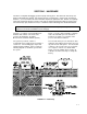
SECTION 1. HARDWARE The PST is a complete datalogging system for pump and slug tests. The PST3 can measure up to 3 wells and the PST8 up to 8 wells. This manual consists of 2 major parts. The first part, consisting of Sections 1, 2, and 3, contains the basic information required to operate the PST. Section 3 is a prompt sheet to be carried into the field. It leads a user step by step through the procedure for running a test.
SECTION 1. HARDWARE FIGURE 1-2.
SECTION 1. HARDWARE FIGURE 1-3. Using the Cable Grip to Mount the Transducer FIGURE 1-4.
SECTION 1. HARDWARE FIGURE 1-5.
SECTION 1. HARDWARE FIGURE 1-6. Test Configuration Switches Method of Recording Data DELTA LOGARITHMIC The sensors are scanned and data are recorded on a logarithmic time sequence. See Sec. 4 for details. Time and water level are recorded whenever the level changes by a specified delta value. The USER selects the delta value. Default is 0.25 (feet or meters). See Sec. 4 for details. Recording Time ELAPSED TIME CLOCK TIME Time is recorded as the time ELAPSED since the beginning of the test.
SECTION 1. HARDWARE After Sensor Installation SCAN OFF ON The sensors can be scanned before the test is started. No data are recorded when scanning. Set the switch to OFF when scanning is completed; scanning sensors uses battery power. During a test, this switch is inoperative. Running a Test Recording OFF ON Starts and stops a test. Begin the test by setting the recording switch to the "ON" position.
SECTION 2. SOFTWARE There are 2 major software items in the PST system: • Datalogger software to operate the CR10, make the measurements and store data in the Final Storage in the CR10 (and the Storage Module if one is being used). • PC software (PC208 and PCPST) to aid in setup and data retrieval to an ASCII file in a PC. Once the file is stored in the PC, analysis can begin. Commercial analysis software is a separate item which must be purchased by the user.
SECTION 2. SOFTWARE diskette 1 in floppy drive A: and enter the following: install Follow the directions provided on the screen as the installation proceeds. Remember to install the programs into subdirectory "PST." Remove and insert subsequent diskettes as requested. The first time you run PCPST after installing it on your hard drive, you may need to set the communications port (default is COM1). The option for changing your communications port is in the utility menu. 2.2.
SECTION 2. SOFTWARE the PST well number (y = S means all wells) E. Convert WELL.DAT elapsed time data to .PRN analysis software format TSTxxWLy.RPT Printable file with page and column headings, page numbers and printer form feed characters TSTxxWLy.PRN File ready to import into spreadsheet or database programs When the user selects this menu item, PCPST will convert the raw data file named WELL.DAT into individual well test .
SECTION 2. SOFTWARE I. Get data from storage module to WELL.DAT 1. This item allows the user to collect data from an SM192 or SM716 storage module. First, PCPST uses PC208/GraphTerm to ensure that the PST has finished transferring data to the storage module. Then, PCPST uses PC208/TELCOM to collect the data from the storage module. The storage module must be connected to a PST for this operation. Data can be converted using utilities menu option E or F. 2.
3.0 STEP BY STEP PROCEDURE FOR A PUMP OR SLUG TEST. 3.1 The day before a test Connect the PST to 115 VAC via the AC adapter to "top off" the battery. After several hours or overnight, disconnect. Connect the pressure transducer(s), enter the multiplier(s) - see *4 Table, below. Verify reasonable readings. Check desiccant box. Verify tight connections in terminal strip. Confirm the presence of desiccant (this should be changed every 3-6 months) and porous plastic filter (see Figure 1-1, Section 1). 3.
SECTION 3. TEST PROCEDURE Or using a laptop Run the program PST. Select option C in the Utilities menu. Measure the water level manually Measure and note the water level in each well using a chalked tape, beeper, etc. Install the PRESSURE TRANSDUCERS in the wells In each well to be monitored: - Measure the length of the pressure transducer cable to be installed down the well. - Install the pressure transducer in the well. Suggested method of mounting in Figure 1-3, Section 1.
SECTION 3.
SECTION 3. TEST PROCEDURE 6 . . . . . . . . . . . . Offset, well #1 (Engr. units) 7 . . . . . . . . . . . . Delta threshold, well #2 8 . . . . . . . . . . . . Multiplier, well #2 9 . . . . . . . . . . . . Offset, well #2 10 . . . . . . . . . . . Delta threshold, well #3 11 . . . . . . . . . . . Multiplier, well #3 12 . . . . . . . . . . . Offset, well #3 13 . . . . . . . . . . . Final logarithmic interval in seconds 14 . . . . . . . . . . . Exc. code, transducer #1 15 . . . . . . . . . . . Exc.
SECTION 3. TEST PROCEDURE 28 . . . . . . . . . . . Final logarithmic interval in seconds 29 . . . . . . . . . . . Exc. code, transducer #1 30 . . . . . . . . . . . Exc. code, transducer #2 31 . . . . . . . . . . . Exc. code, transducer #3 Excitation Code 0 for sensors from 5-20 psi 1 for sensors over 20 psi 32 . . . . . . . . . . . Exc. code, transducer #4 33 . . . . . . . . . . . Exc. code, transducer #5 34 . . . . . . . . . . . Exc. code, transducer #6 35 . . . . . . . . . . . Exc.
SECTION 3. TEST PROCEDURE PST3 *6 Location 1 . . . . . . . . . .Level well #1 2 . . . . . . . . . .Level well #2 3 . . . . . . . . . .Level well #3 4 . . . . . . . . . .Location ID # 5 . . . . . . . . . .Number of wells NOTE: These values are updated only if the SCAN or RECORDING switch is on. 6 . . . . . . . . . .Battery voltage 35 . . . . . . . . .Elapsed time PST8 *6 Location 1 . . . . . . . . . .Level well #1 2 . . . . . . . . . .Level well #2 3 . . . . . . . . . .Level well #3 4 . . . . . . . . . .
SECTION 3. TEST PROCEDURE Scan the sensors again to verify the offset Correct the offset if necessary. Turn off the scan switch Ready to begin the test. 3.3 Begin the test Turn the recording switch to the "ON" position at the same time the pumps are turned on or the slug is inserted. Logarithmic Logarithmic - data collection begins when the switch is turned to "ON". Delta Delta - the elapsed time starts when the switch is turned to "ON".
SECTION 3. TEST PROCEDURE 3.5 *7 Mode Displaying Final Readings Recorded data can be verified from the keyboard/display in *7 mode. Data retrieval should be done with a PC running PCPST. 07:XXXX where XXXX is the next location in the ring memory where data will be stored.
SECTION 3.
SECTION 4. TECHNICAL DETAILS - HARDWARE 4.1 STORAGE MODULE An optional SM192 or SM716 storage module can be used to collect data from the PST or to provide additional memory capacity. A bracket is available (PST-BKT) for mounting the storage module to the PST. To collect data, simply plug the storage module into the connector for the CR10KD keyboard/display. An SC90 line monitor can be used to monitor when the data collection is complete.
SECTION 4. TECHNICAL DETAILS TABLE 4.2-1. Keller-PSI Calibration Report Customer: Model No: Serial No: Pressure Range: Excitation: Output: Campbell Scientific 169-110-0051 93907 0 to 15 PSIG .5 mA 0-60 mV Test Date: Text Excitation Test Temperatures: Test Pressure PSIG BFSL Rm Temp Outputs ------- Run #1 ------Rm Temp Error Outputs %FSO 0.00 3.00 6.00 9.00 12.00 15.00 12.00 9.00 6.00 3.00 0.00 0.14 9.55 18.96 28.37 37.78 47.19 37.78 28.37 18.96 9.55 0.14 0.176 9.519 18.921 28.358 37.801 47.222 37.
SECTION 4. TECHNICAL DETAILS - HARDWARE threshold is 0.25. The units are determined by the multiplier used for the pressure transducer. In Delta sampling, measurements are made at regular intervals. The default sampling interval is 0.25 seconds. It can be changed in the *4 Table to 0.5 seconds or 1.0 seconds. The default value gives the greatest resolution. Example: If the Delta threshold is set to 0.1 feet and the water level drops 1 foot, 10 data records would be stored.
SECTION 4. TECHNICAL DETAILS by the number of data points used each recording. Number of Wells 1 2 3 4 5 6 7 8 Data Points 3 4 5 6 7 8 9 10 Total # of Records 9966 7475 5980 4983 4271 3737 3322 2990 To calculate the total time to fill the memory, the execution interval must be considered. Six different time intervals between samples are used during the course of the test. During the first 1000 minutes, 251 recordings are made.
SECTION 5. TECHNICAL DETAILS - SOFTWARE 5.1 README FILE This file contains the full text of the users manual for PCPST menu software. It briefly describes the contents of the Campbell Scientific PCPST diskette and how to install the software on a computer. This file may also be viewed on the computer screen after installing PCPST by entering "readme" at the DOS prompt. 5.2 INSTALLATION 5.2.1 WORKING COPY An example of a DOS command to make a working copy of the diskette in drive A: follows: 1.
SECTION 5. TECHNICAL DETAILS 1= 2= 3= 4= 5= 6= EDLOG Datalogger Program Editor GRAPHTERM Terminal Emulator TELCOM Data Collection Program SPLIT Data Split/Merge Program SMCOM Storage Module Communications (SM192/716) All of the above Enter a list of digits corresponding to what you want installed: HARD DISK If installing the PC208 software on a hard disk or a diskette with 1.2 megabytes or greater, then select 6 to install all the programs on the specific drive.