HMP50 Temperature and Relative Humidity Probe Revision: 10/09 C o p y r i g h t © 1 9 9 5 - 2 0 0 9 C a m p b e l l S c i e n t i f i c , I n c .
Warranty and Assistance The HMP50 TEMPERATURE AND RELATIVE HUMIDITY PROBE is warranted by CAMPBELL SCIENTIFIC, INC. to be free from defects in materials and workmanship under normal use and service for twelve (12) months from date of shipment unless specified otherwise. Batteries have no warranty. CAMPBELL SCIENTIFIC, INC.'s obligation under this warranty is limited to repairing or replacing (at CAMPBELL SCIENTIFIC, INC.'s option) defective products.
HMP50 Table of Contents PDF viewers note: These page numbers refer to the printed version of this document. Use the Adobe Acrobat® bookmarks tab for links to specific sections. 1. General .........................................................................1 2. Specifications ..............................................................1 2.1 Temperature Sensor ..................................................................................2 2.2 Relative Humidity Sensor...............................
HMP50 Table of Contents Tables 1. 2. 3. 4. 5. 6. Recommended Lead Lengths..................................................................... 1 Datalogger Connections............................................................................. 6 Calibration for Temperature....................................................................... 7 Calibration for Relative Humidity ............................................................. 7 Wiring for CR1000 and CR10X Examples............................
HMP50 Temperature and Relative Humidity Probe 1. General The HMP50 Temperature and Relative Humidity probe contains a Platinum Resistance Temperature detector (PRT) and a Vaisala INTERCAP® capacitive relative humidity sensor. The -L option on the model HMP50 Temperature and Relative Humidity probe (HMP50-L) indicates that the cable length is user specified. Lead length is specified when the sensor is ordered. Table 1 gives the recommended lead length. This manual refers to the sensor as the HMP50. TABLE 1.
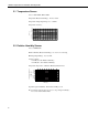
HMP50 Temperature and Relative Humidity Probe 2.1 Temperature Sensor Sensor: 1000 Ω PRT, DIN 43760B Temperature Measurement Range: -40°C to +60°C Temperature Output Signal range: 0 to 1.0 VDC Error ( o C) Temperature Accuracy: 1.6 1.2 0.8 0.4 0 -0.4 -0.8 -1.2 -1.6 -40 -20 0 20 Temperature ( o 40 60 C) 2.2 Relative Humidity Sensor Sensor: INTERCAP® Relative Humidity Measurement Range: 0 to 98% non-condensing RH Output Signal Range: 0 to 1.
HMP50 Temperature and Relative Humidity Probe 3. Installation 3.1 Siting Sensors should be located over an open level area at least 9 m (EPA) in diameter. The surface should be covered by short grass, or where grass does not grow, the natural earth surface. Sensors should be located at a distance of at least four times the height of any nearby obstruction, and at least 30 m (EPA) from large paved areas. Sensors should be protected from thermal radiation, and adequately ventilated.
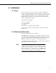
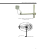
HMP50 Temperature and Relative Humidity Probe Yellow Shipping Cap (remove before installation) FIGURE 1. HMP50 as Shipped FIGURE 2.
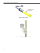
HMP50 Temperature and Relative Humidity Probe FIGURE 3. HMP50 and 41303-5A Radiation Shield on a CM202 Crossarm Mounting Clamp FIGURE 4.
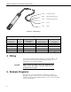
HMP50 Temperature and Relative Humidity Probe Black Temperature Signal White Relative Humidity Signal Blue Signal & Power Reference Brown Power Clear Shield FIGURE 5. HMP50 Wiring TABLE 2.
HMP50 Temperature and Relative Humidity Probe The temperature and relative humidity signals from the HMP50 are measured using two single-ended analog measurements (Instruction 1). The probe output scale is 0 to 1000 millivolts for the temperature range of -40°C to +60°C and for the relative humidity range of 0 to 100%. Tables 3 and 4 provide calibration information for temperature and relative humidity. TABLE 3. Calibration for Temperature Units Celsius Fahrenheit Multiplier (degrees mV-1) 0.1 0.
HMP50 Temperature and Relative Humidity Probe BeginProg Scan(5,Sec,1,0) 'HMP50 Temperature & Relative Humidity Sensor measurements AirTC and RH: VoltSE(AirTC,1,mV2500,1,0,0,_60Hz,0.1,-40.0) VoltSE(RH,1,mV2500,2,0,0,_60Hz,0.1,0) If (RH>100) And (RH<108) Then RH=100 CallTable(Table1) NextScan EndProg 5.2 Example for CR10X ;Measure the HMP50 temperature. ; 01: Volt (SE) (P1) 1: 1 Reps 2: 5 2500 mV Slow Range 3: 4: 5: 6: 3 1 .
HMP50 Temperature and Relative Humidity Probe 6. Long Lead Lengths Long lead lengths cause errors in the measured temperature and relative humidity. The approximate error in temperature and relative humidity is 0.52°C and 0.52% per 100 feet of cable length, respectively. When long lead lengths are required and the above errors in temperature and relative humidity are unacceptable, use the HMP45C temperature and humidity probe.
HMP50 Temperature and Relative Humidity Probe When the air temperature increases, so does the saturation vapor pressure. Conversely, a decrease in air temperature causes a corresponding decrease in saturation vapor pressure. It follows then from Eq. (2) that a change in air temperature will change the relative humidity, without causing a change in absolute humidity. For example, for an air temperature of 20°C and a vapor pressure of 1.17 kPa, the saturation vapor pressure is 2.
HMP50 Temperature and Relative Humidity Probe 'CR1000 Public AirTC Public RH Public VP DataTable(Table1,True,-1) DataInterval(0,60,Min,0) Average(1,AirTC,FP2,0) Sample(1,RH,FP2) Average(1,VP, FP2,0) EndTable BeginProg Scan(5,Sec,1,0) 'HMP50 Temperature & Relative Humidity Sensor measurements AirTC and RH: VoltSE(AirTC,1,mV2500,1,0,0,_60Hz,0.1,-40.0) VoltSE(RH,1,mV2500,2,0,0,_60Hz,0.1,0) If (RH>100) And (RH<108) Then RH=100 VaporPressure(VP,AirTC,RH) CallTable(Table1) NextScan EndProg 7.
HMP50 Temperature and Relative Humidity Probe ;Limit the maximum value of relative humidity ;to 1 (expressed as a fraction). ; 03: If (X<=>F) (P89) 1: 2 X Loc [ RH_frac ] 2: 3 >= 3: 1 F 4: 30 Then Do 04: Z=F (P30) 1: 1 2: 0 3: 2 F Exponent of 10 Z Loc [ RH_frac ] 05: End (P95) ;Compute the saturation vapor pressure in kPa. ;The temperature must be in degrees Celsius. ; 06: Saturation Vapor Pressure (P56) 1: 1 Temperature Loc [ T_C ] 2: 3 Loc [ e_sat ] ;Compute the vapor pressure in kPa.
HMP50 Temperature and Relative Humidity Probe Protective Cap and Filter Shipping Cap (remove prior to installation) 9598 RH Chip FIGURE 6. Exploded View of HMP50 (as shipped) The offset and gain on the HMP50 electronics can not be adjusted as part of a recalibration. Replace the RH chip as needed. 8.1 Procedure for Removing RH Chip 1. Unscrew the protective cap. 2. Hold the plastic sides of the RH chip and unplug it.
HMP50 Temperature and Relative Humidity Probe 14
Campbell Scientific Companies Campbell Scientific, Inc. (CSI) 815 West 1800 North Logan, Utah 84321 UNITED STATES www.campbellsci.com • info@campbellsci.com Campbell Scientific Africa Pty. Ltd. (CSAf) PO Box 2450 Somerset West 7129 SOUTH AFRICA www.csafrica.co.za • cleroux@csafrica.co.za Campbell Scientific Australia Pty. Ltd. (CSA) PO Box 444 Thuringowa Central QLD 4812 AUSTRALIA www.campbellsci.com.au • info@campbellsci.com.au Campbell Scientific do Brazil Ltda.