INSTRUCTION MANUAL Model HFP01SC Self-Calibrating Soil Heat Flux Plate Revision: 3/14 C o p y r i g h t © 2 0 0 2 - 2 0 1 4 C a m p b e l l S c i e n t i f i c , I n c .
Warranty “PRODUCTS MANUFACTURED BY CAMPBELL SCIENTIFIC, INC. are warranted by Campbell Scientific, Inc. (“Campbell”) to be free from defects in materials and workmanship under normal use and service for twelve (12) months from date of shipment unless otherwise specified in the corresponding Campbell pricelist or product manual. Products not manufactured, but that are re-sold by Campbell, are warranted only to the limits extended by the original manufacturer.
Assistance Products may not be returned without prior authorization. The following contact information is for US and international customers residing in countries served by Campbell Scientific, Inc. directly. Affiliate companies handle repairs for customers within their territories. Please visit www.campbellsci.com to determine which Campbell Scientific company serves your country. To obtain a Returned Materials Authorization (RMA), contact CAMPBELL SCIENTIFIC, INC., phone (435) 227-9000.
Table of Contents PDF viewers: These page numbers refer to the printed version of this document. Use the PDF reader bookmarks tab for links to specific sections. 1. Introduction ................................................................. 1 2. Cautionary Statements ............................................... 1 3. Initial Inspection ......................................................... 1 4. Overview ...................................................................... 1 5. Specifications .....
Table of Contents ii
Model HFP01SC Self-Calibrating Soil Heat Flux Plate 1. Introduction The HFP01SC Self-Calibrating Heat Flux Sensor measures soil heat flux, typically for energy-balance or Bowen-ratio flux systems. It is intended for applications requiring the highest possible degree of measurement accuracy. At least two sensors are required for each site to provide spatial averaging. Sites with heterogeneous media may require additional sensors.
Model HFP01SC Self-Calibrating Soil Heat Flux Plate In order to measure soil heat flux at the surface, several HFP01SCs are used to measure the soil heat flux at a depth of eight centimeters. A TCAV, Averaging Soil Thermocouple, is used to measure the temporal change in temperature of the soil layer above the HFP01SC. Finally, a CS650, CS655, or CS616 water content reflectometer is used to measure the soil water content.
Model HFP01SC Self-Calibrating Soil Heat Flux Plate 6. Sensor: Thermopile and film heater Heater Voltage Input: 9 to 15 Vdc Heater Voltage Output: 0 to 2 Vdc Expected Accuracy: ±3% of reading Sensitivity (nominal): 50 µV W–1 m–2 Sensor Resistance (nominal): 2Ω Heater Resistance (nominal): 100 Ω Duration of Calibration: ±3 min. @ 1.5 W; typically done every 3 to 6 hours Weight without Cable: 200 g (7.05 oz) Installation 6.
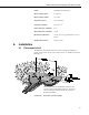
Model HFP01SC Self-Calibrating Soil Heat Flux Plate The location of the heat flux plates and thermocouples should represent the area of study. If the ground cover is extremely varied, it may be necessary to have additional sensors to provide a valid spatial average of soil heat flux. Use a small shovel to make a vertical slice in the soil. Excavate the soil to one side of the slice. Keep this soil intact to ensure replacement with minimal disruption.
Model HFP01SC Self-Calibrating Soil Heat Flux Plate TABLE 6-1.
Model HFP01SC Self-Calibrating Soil Heat Flux Plate 6.2 Wiring Connections to Campbell Scientific dataloggers are given in FIGURE 6-1, TABLE 6-1, and TABLE 6-2. The output of the HFP01SC can be measured using a single-ended analog measurement (VoltSE() or Instruction 1), however, a differential analog measurement (VoltDiff() or Instruction 2) is recommended.
Model HFP01SC Self-Calibrating Soil Heat Flux Plate Heater Resistor Signal #1 Yellow 13H Heater Resistor Signal Reference #1 Purple Shield #1 Clear Power #1 Red SW12-1 Power Reference #1 Black G Heater Resistor Signal #2 Yellow 13L Heater Resistor Signal Reference #2 Purple Shield #2 Clear Power #2 Red SW12-1 Power Reference #2 Black G Heater Resistor Signal #3 Yellow 14H Heater Resistor Signal Reference #3 Purple Shield #3 Clear Power #3 Red SW12-1 Power Reference #3 B
Model HFP01SC Self-Calibrating Soil Heat Flux Plate BeginProg 'HFP01SC factory calibration in W/(m^2 mV) = 1000/sensitivity. shf_cal(1) = HFP01SC_CAL_1 shf_cal(2) = HFP01SC_CAL_2 shf_cal(3) = HFP01SC_CAL_3 shf_cal(4) = HFP01SC_CAL_4 Scan (1,Sec,3,0) 'Measure the HFP01SC soil heat flux plates. VoltDiff (shf_mV(1),4,mV50C,9,TRUE,0,_60Hz,1,0) 'Apply calibration to HFP01SC soil heat flux plates. For ii = 1 To 4 shf(ii) = shf_mV(ii)*shf_cal(ii) Next ii 'Power the HFP01SC heaters.
Model HFP01SC Self-Calibrating Soil Heat Flux Plate 6.3.2 Example 2. Sample CR10(X) Program Using a Single-Ended Measurement Instruction TABLE 6-4 provides the wiring for Example 2. TABLE 6-4.
Model HFP01SC Self-Calibrating Soil Heat Flux Plate ;Factory calibration in W/(m^2 mV) = 1000/sensitivity. ; 4: Z=F (P30) 1: 1 F ; <- Enter the unique calibration here 2: 0 Exponent of 10 3: 3 Z Loc [ cal ] 5: End (P95) ;Use data from the larger measurement range. ; 6: If (X<=>F) (P89) 1: 2 X Loc [ shf_mV ] 2: 4 < 3: -99990 F 4: 30 Then Do 7: Z=X (P31) 1: 8 2: 2 8: X Loc [ shf_mV_a Z Loc [ shf_mV ] ] End (P95) ;Apply custom calibration to the raw soil heat flux measurement.
Model HFP01SC Self-Calibrating Soil Heat Flux Plate *Table 2 Program 02: 0 Execution Interval (seconds) *Table 3 Subroutines ;Calibration routine. ; 1: Beginning of Subroutine (P85) 1: 8 Subroutine 8 ;Perform in-situ calibration. ; 2: If time is (P92) 1: 1 Minutes (Seconds --) into a 2: 180 Interval (same units as above) 3: 30 Then Do 3: Z=X (P31) 1: 2 2: 4 X Loc [ shf_mV Z Loc [ mV_0 ] ] ;Begin heating for calibration.
Model HFP01SC Self-Calibrating Soil Heat Flux Plate ;Stop filtering data. ; 12: If time is (P92) 1: 39 Minutes (Seconds --) into a 2: 180 Interval (same units as above) 3: 30 Then Do 13: Do (P86) 1: 28 Set Flag 8 Low ;Compute in-situ calibration. ; 14: Z=X (P31) 1: 2 X Loc [ shf_mV 2: 6 Z Loc [ mV_end ] ] 15: Z=X*Y (P36) 1: 7 X Loc [ V_Rf 2: 7 Y Loc [ V_Rf 3: 3 Z Loc [ cal ] ] ] 16: Z=X*F (P37) 1: 3 X Loc [ cal 2: 128.
Model HFP01SC Self-Calibrating Soil Heat Flux Plate 6.3.3 Example 3. Sample CR23X Program Using a Differential Measurement Instruction TABLE 6-5 provides the wiring for Example 3. TABLE 6-5.
Model HFP01SC Self-Calibrating Soil Heat Flux Plate ;Factory calibration in W/(m^2 mV) = 1000/sensitivity. ; 4: Z=F (P30) 1: 1 F ; <- Enter the unique calibration here 2: 0 Exponent of 10 3: 3 Z Loc [ cal ] 5: End (P95) ;Use data from the larger measurement range. ; 6: If (X<=>F) (P89) 1: 2 X Loc [ shf_mV ] 2: 4 < 3: -99990 F 4: 30 Then Do 7: Z=X (P31) 1: 8 2: 2 8: X Loc [ shf_mV_a Z Loc [ shf_mV ] ] End (P95) ;Apply custom calibration to the raw soil heat flux measurement.
Model HFP01SC Self-Calibrating Soil Heat Flux Plate *Table 2 Program 02: 0 Execution Interval (seconds) *Table 3 Subroutines ;Calibration routine. ; 1: Beginning of Subroutine (P85) 1: 8 Subroutine 8 ;Perform in-situ calibration. ; 2: If time is (P92) 1: 1 Minutes (Seconds --) into a 2: 180 Interval (same units as above) 3: 30 Then Do 3: Z=X (P31) 1: 2 2: 4 X Loc [ shf_mV Z Loc [ mV_0 ] ] ;Begin heating for calibration.
Model HFP01SC Self-Calibrating Soil Heat Flux Plate 13: Do (P86) 1: 218 Set Flag 18 Low ;Compute in-situ calibration. ; 14: Z=X (P31) 1: 2 X Loc [ shf_mV 2: 6 Z Loc [ mV_end ] ] 15: Z=X*Y (P36) 1: 7 X Loc [ V_Rf 2: 7 Y Loc [ V_Rf 3: 3 Z Loc [ cal ] ] ] 16: Z=X*F (P37) 1: 3 X Loc [ cal 2: 128.7 F 3: 3 Z Loc [ cal 17: Z=X+Y (P33) 1: 4 X Loc [ mV_0 2: 6 Y Loc [ mV_end 3: 9 Z Loc [ work ] ] ] ] 18: Z=X*F (P37) 1: 9 X Loc [ work 2: .
Model HFP01SC Self-Calibrating Soil Heat Flux Plate 6.3.4 Example 4. Sample CR10X Program Using External Power and Relay TABLE 6-6 provides the sensor wiring for Example 4, and TABLE 6-7 provides the datalogger wiring for Example 4. TABLE 6-6.
Model HFP01SC Self-Calibrating Soil Heat Flux Plate ;{CR10X} ; *Table 1 Program 01: 1 Execution Interval (seconds) ;Measure HFP01SC on smallest range. ; 1: Volt (SE) (P1) 1: 6 Reps 2: 22 7.5 mV 60 Hz Rejection Range 3: 1 SE Channel 4: 7 Loc [ shf_mV_1 ] 5: 1 Mult 6: 0 Offset ;Measure HFP01SC on larger range. ; 2: Volt (SE) (P1) 1: 6 Reps 2: 23 25 mV 60 Hz Rejection Range 3: 1 SE Channel 4: 44 Loc [ shf_mV_1a ] 5: 1 Mult 6: 0 Offset ;Load in the factory calibration.
Model HFP01SC Self-Calibrating Soil Heat Flux Plate 11: Beginning of Loop (P87) 1: 0 Delay 2: 6 Loop Count ;Use data from the larger measurement range. ; 12: If (X<=>F) (P89) 1: 7 -X Loc [ shf_mV_1 ] 2: 4 < 3: -99990 F 4: 30 Then Do 13: Z=X (P31) 1: 44 -2: 7 -14: X Loc [ shf_mV_1a ] Z Loc [ shf_mV_1 ] End (P95) ;Apply custom calibration to raw soil heat flux measurement. ; 15: Z=X*Y (P36) 1: 7 -X Loc [ shf_mV_1 ] 2: 13 -Y Loc [ cal_1 ] 3: 1 -Z Loc [ shf_1 ] 16: End (P95) ;Output data.
Model HFP01SC Self-Calibrating Soil Heat Flux Plate *Table 3 Subroutines ;Calibration routine. ; 1: Beginning of Subroutine (P85) 1: 8 Subroutine 8 ;Perform in-situ calibration. ; 2: If time is (P92) 1: 1 Minutes (Seconds --) into a 2: 180 Interval (same units as above) 3: 30 Then Do 3: Beginning of Loop (P87) 1: 0 Delay 2: 6 Loop Count 4: Z=X (P31) 1: 7 -2: 19 -5: X Loc [ shf_mV_1 Z Loc [ mV_0_1 ] ] End (P95) ;Begin heating for calibration.
Model HFP01SC Self-Calibrating Soil Heat Flux Plate 15: End (P95) ;Compute in-situ calibration. ; 16: If time is (P92) 1: 39 Minutes (Seconds --) into a 2: 180 Interval (same units as above) 3: 30 Then Do 17: Do (P86) 1: 28 Set Flag 8 Low 18: Beginning of Loop (P87) 1: 0 Delay 2: 6 Loop Count 19: Z=X (P31) 1: 7 -2: 31 -- X Loc [ shf_mV_1 Z Loc [ mV_end_1 20: Z=X*Y (P36) 1: 37 -X Loc [ V_Rf_1 2: 37 -Y Loc [ V_Rf_1 3: 13 -Z Loc [ cal_1 21: Z=X*F (P37) 1: 13 -X Loc [ cal_1 2: 128.
Model HFP01SC Self-Calibrating Soil Heat Flux Plate 5 shf_5 0 0 0 6 shf_6 0 0 0 7 shf_mV_1 1 5 2 8 shf_mV_2 1 0 1 9 shf_mV_3 1 0 1 10 shf_mV_4 1 0 1 11 shf_mV_5 1 0 1 12 shf_mV_6 1 0 1 13 cal_1 5 5 3 14 cal_2 9 0 1 15 cal_3 9 0 1 16 cal_4 9 0 1 17 cal_5 9 0 1 18 cal_6 9 0 1 19 mV_0_1 9 1 1 20 mV_0_2 1 0 0 21 mV_0_3 0 0 0 22 mV_0_4 0 0 0 23 mV_0_5 0 0 0 24 mV_0_6 0 0 0 25 mV_180_1 1 1 1 26 mV_180_2 0 0 0 27 mV_180_3 0 0 0 28 mV_180_4 0 0 0 29 mV_180_5 0 0 0 30 mV_180_6 0 0 0 31 mV_end_1 1 1 1 32 mV_end_2 0
Model HFP01SC Self-Calibrating Soil Heat Flux Plate θm = ρw θv ρb (2) where CS is the heat capacity of moist soil, ρb is the bulk density, ρw is the density of water, Cd is the heat capacity of a dry mineral soil, θm is the soil water content on a mass basis, θv is the soil water content on a volume basis, and Cw is the heat capacity of water.
Model HFP01SC Self-Calibrating Soil Heat Flux Plate TABLE 6-8. Hukseflux and Campbell Scientific Variable Names 7.
Campbell Scientific Companies Campbell Scientific, Inc. (CSI) 815 West 1800 North Logan, Utah 84321 UNITED STATES www.campbellsci.com • info@campbellsci.com Campbell Scientific Africa Pty. Ltd. (CSAf) PO Box 2450 Somerset West 7129 SOUTH AFRICA www.csafrica.co.za • cleroux@csafrica.co.za Campbell Scientific Australia Pty. Ltd. (CSA) PO Box 8108 Garbutt Post Shop QLD 4814 AUSTRALIA www.campbellsci.com.au • info@campbellsci.com.au Campbell Scientific do Brasil Ltda. (CSB) Rua Apinagés, nbr.