
Owner's manual
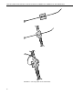
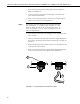
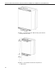
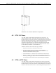
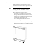
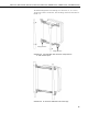
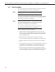
Table Of Contents
- Revision and Copyright Information
- Warranty
- Assistance
- Table of Contents
- 1. General Description
- 2. Enclosure Supply Kit
- 3. Mounting Equipment Inside the Enclosure
- 4. Attachment to an Instrument Mount
- 5. When to Replace Desiccant
- 6. Resistance to Weathering
- Appendix A. Door Switch
- Appendix B. 25458/28532 DIN-Rail Terminal Kits
- Appendix C. 28960 Stack Mounting Kit
- Appendix D. Keeping Insects Out Of the Enclosure
- Campbell Scientific Companies
ENC10/12, ENC10/12R, ENC12/14, ENC14/16, ENC16/18, PWENC12/14, PWENC14/16, and PWENC16/18
The default configuration is for attaching to a UT10 tower (i.e., D = 10.25").
To attach to a UT20 or UT30 tower, move the flange sections of the bracket so
that D = 17".
Flange Section
Flange Section
FIGURE 4-5. This exploded view shows the components of
a “-TM” bracket option
FIGURE 4-6. An enclosure attached to two tower legs
13