
Manual
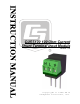


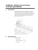

Table Of Contents

Table of Contents
PDF viewers: These page numbers refer to the printed version of this document. Use the
PDF reader bookmarks tab for links to specific sections.
1. Introduction.................................................................1
2. Specifications .............................................................1
3. Measurement Concepts .............................................2
3.1 Differential Measurement ....................................................................3
3.2 Completing the Current Loop Circuit ..................................................3
4. Transducer Wiring ......................................................4
4.1 Two-Wire Transducers.........................................................................4
4.1.1 Possible Ground Loop Problems...................................................5
4.1.2 Minimum Supply Voltage.............................................................5
4.2 Three-Wire Transducers.......................................................................6
4.3 Four-Wire Transducers ........................................................................7
5. Sensor and Programming Example ..........................8
5.1 Voltage Range......................................................................................8
5.2 Calculating Multiplier and Offset—An Example.................................8
5.3 CR1000 Program Example...................................................................9
5.4 CR9000(X) Program Example ...........................................................10
5.5 CR10(X) Program Example...............................................................10
5.6 CR23X Program Example..................................................................10
Figures
1-1. CURS100 terminal input module.........................................................1
2-1. CURS100 schematic ............................................................................2
3-1. CURS100 L terminal connected to a datalogger G terminal using
a jumper wire....................................................................................4
4-1. 2-wire with datalogger power ..............................................................5
4-2. 2-wire with external power ..................................................................5
4-3. 2-wire supply voltage...........................................................................6
4-4. 3-wire with datalogger power ..............................................................6
4-5. 3-wire with external power ..................................................................7
4-6. 4-wire with datalogger power ..............................................................7
4-7. 4-wire with external power ..................................................................7
i