CS431 Submersible Pressure Transducer Revision: 3/09 C o p y r i g h t © 2 0 0 8 - 2 0 0 9 C a m p b e l l S c i e n t i f i c , I n c .
Warranty and Assistance The CS431 SUBMERSIBLE PRESSURE TRANSDUCER is warranted by CAMPBELL SCIENTIFIC, INC. to be free from defects in materials and workmanship under normal use and service for twelve (12) months from date of shipment unless specified otherwise. Batteries have no warranty. CAMPBELL SCIENTIFIC, INC.'s obligation under this warranty is limited to repairing or replacing (at CAMPBELL SCIENTIFIC, INC.'s option) defective products.
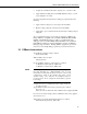
CS431 Table of Contents PDF viewers note: These page numbers refer to the printed version of this document. Use the Adobe Acrobat® bookmarks tab for links to specific sections. 1. General Description.....................................................1 2. Specifications ..............................................................1 3. Installation....................................................................2 3.1 3.2 3.3 3.4 3.5 Initial Inspection ..................................................
CS431 Table of Contents Figures 4.1. Typical Pressure Element Wiring .......................................................... 3 4-2. Typical Temperature Element Wiring .................................................... 4 6-1. Desiccant Tube ..................................................................................... 13 Tables 5-1. CR1000 Connections for Example Programs.........................................
CS431 Submersible Pressure Transducer 1. General Description The CS431 PS9805 Pressure Transducer is manufactured by Instrumentation Northwest for use with Campbell Scientific dataloggers. It uses piezoresistive strain gage technology to measure water level and an on-board thermistor to measure temperature. Piezoresistive transducers include a strain gage bonded to a pressure-sensitive diaphragm. Electrical resistance changes as pressure changes on the diaphragm.
CS431 Submersible Pressure Transducer 3. Installation 3.1 Initial Inspection Upon receipt of the CS431, inspect the packaging for any signs of shipping damage and, if found, report the damage to the carrier in accordance with policy. The contents of the package should also be inspected and a claim filed if any shipping related damage is discovered. Care should be taken when opening the package not to damage or cut the cable jacket.
CS431 Submersible Pressure Transducer 3.5 Other Installations The CS431 can be installed in any position; however, when it leaves the factory it is tested in the vertical position. Strapping the transducer body with tie wraps or tape will not hurt it. If the CS431 is being installed in a fluid environment other than water, check the compatibility of the fluid with the wetted parts of the probe. Because the CS431 is vented, a desiccant tube must always be attached to the CS431.
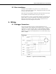
CS431 Submersible Pressure Transducer FIGURE 4-2. Typical Temperature Element Wiring 4.2 Grounding CAUTION Proper grounding is very important! To prevent grounding issues, do the following: (1) Attach the sensor cable shield (the wrapped shield inside the cable) to the power ground (G terminal) on the datalogger. (2) Use a 12 AWG or larger wire to connect the datalogger’s grounding lug with a grounding rod that has been driven into the earth.
CS431 Submersible Pressure Transducer • Compute the normalized ratiometric output (L) as: L = (Vo/Vr) * 100. • Apply calibration/scaling values (from INW calibration sheet) to convert to psi: multiplier * L + offset. To get the temperature measurement, the datalogger program should do the following: • Apply excitation voltage across T1 (orange) and AG (black). • Measure voltage output across T2 (brown) and AG (black).
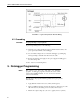
CS431 Submersible Pressure Transducer This function is designed for the thermistor used in the CS431. It automatically selects the excitation voltage and processes the result using the Steinhart-Hart calculation to get an output in degrees centigrade. 5.1.1 Example CRBasic Programs The following two examples are for the CR1000 but other CRBasic dataloggers are programmed similarly. Table 5-1 shows the wiring used for these examples. TABLE 5-1.
CS431 Submersible Pressure Transducer Public Temp(2) Public L(2) Public P(2) 'temperature, one per sensor 'L factor (Vo/Vr * 100), one per sensor 'Standard calibrated pressure in psi, one per sensor Public Batt_volt Units Batt_Volt=Volts 'Define Data Tables DataTable(Table1,True,-1) DataInterval(0,500,msec,10) Sample(1,Batt_Volt, IEEE4) Sample(4,V(),IEEE4) 'battery voltage 'excitation voltage, then output voltage, for each sensor 'For example: V(1)=Vr for 1st sensor, V(2)=Vo for 1st sensor 'V(3)=Vr for
CS431 Submersible Pressure Transducer 5.1.1.
CS431 Submersible Pressure Transducer 'Sensor 2 (typical 15 psig sensor) m2(2) = 0.000000133861 m1(2) = 0.000001790422 m0(2) = 0.192297242812 b2(2) = 0.000040080304 b1(2) = -0.001486634952 b0(2) = 0.176678958007 Scan(500,mSec,1,0) 'scan once every 500 msec ExciteV (Vx1,800,0) 'excite voltage of 800 mV Delay (0,25,mSec) VoltDiff (V(1),1,mV25,1,false,0,_60Hz,1.0,0) 'Vr 1st sensor, diff ch 1 VoltDiff (V(2),1,mV25,2,true,0,_60Hz,1.0,0) 'Vo 1st sensor, diff ch 2 VoltDiff (V(3),1,mV25,4,false,0,_60Hz,1.
CS431 Submersible Pressure Transducer 5.2.1 Example Edlog Programs The following two examples are for the CR10X but other Edlog dataloggers are programmed similarly. 5.2.1.
CS431 Submersible Pressure Transducer 5.2.1.
CS431 Submersible Pressure Transducer 5.2.1.3 Example CR10X PROGRAM – High Precision Measurement for 5 PSI Sensors The Standard and Enhanced Measurement Programming Examples (see Section 5.2.1.1) result in a resolution of ±0.2 inches. These methods use the 25 mV Slow Range of the CR10X. This level of resolution is acceptable for many measurement needs. However, in the 0 – 5 PSI range, greater resolution is often needed.
CS431 Submersible Pressure Transducer ; L can be translated to a pressure measurement using the following formula, ; where m and b (in psi) are determined from device calibration sheet. P=(m)*L + (b) ; Now data can be further processed or written to data storage memory. 6. Maintenance Campbell Scientific recommends that the CS431 be factory recalibrated and checked every six months.
CS431 Submersible Pressure Transducer 7. Troubleshooting 7.1 Erratic Readings Assuming that the datalogger is working properly, the first thing to check is the connection. Look for moisture between contacts or a loose or broken wire. If the connection appears alright, pull the transducer up to a known distance while monitoring its output. If the transducer responds as it should, but the reading is still erratic, most likely the cable is damaged.
CS431 Submersible Pressure Transducer The best method for minimizing ground loops is to tie all equipment (sensors, dataloggers, external power sources and any other associated equipment) to a single common grounding point. To prevent grounding issues, do the following: (1) Attach the sensor cable shield (the wrapped shield inside the cable) to the power ground (G terminal) on the datalogger.
CS431 Submersible Pressure Transducer 16
This is a blank page.
Campbell Scientific Companies Campbell Scientific, Inc. (CSI) 815 West 1800 North Logan, Utah 84321 UNITED STATES www.campbellsci.com info@campbellsci.com Campbell Scientific Africa Pty. Ltd. (CSAf) PO Box 2450 Somerset West 7129 SOUTH AFRICA www.csafrica.co.za cleroux@csafrica.co.za Campbell Scientific Australia Pty. Ltd. (CSA) PO Box 444 Thuringowa Central QLD 4812 AUSTRALIA www.campbellsci.com.au info@campbellsci.com.au Campbell Scientific do Brazil Ltda.