CS110 Electric Field Meter Revision: 4/12 C o p y r i g h t © 2 0 0 5 - 2 0 1 2 C a m p b e l l S c i e n t i f i c , I n c .
Warranty “PRODUCTS MANUFACTURED BY CAMPBELL SCIENTIFIC, INC. are warranted by Campbell Scientific, Inc. (“Campbell”) to be free from defects in materials and workmanship under normal use and service for twelve (12) months from date of shipment unless otherwise specified in the corresponding Campbell product manual. Batteries, fine-wire thermocouples, desiccant, and other consumables have no warranty.
Assistance Products may not be returned without prior authorization. The following contact information is for US and international customers residing in countries served by Campbell Scientific, Inc. directly. Affiliate companies handle repairs for customers within their territories. Please visit www.campbellsci.com to determine which Campbell Scientific company serves your country. To obtain a Returned Materials Authorization (RMA), contact CAMPBELL SCIENTIFIC, INC., phone (435) 227-9000.
CS110 Table of Contents PDF viewers: These page numbers refer to the printed version of this document. Use the PDF reader bookmarks tab for links to specific sections. 1. General Description.....................................................1 1.1 1.2 1.3 1.4 1.5 1.6 CS110 Introduction...................................................................................1 CR1000 Datalogger ..................................................................................2 Meteorological Inputs...............
CS110 Table of Contents 10. Maintenance .............................................................33 10.1 10.2 10.3 10.4 10.5 10.6 10.7 Checking Site Ground Integrity ........................................................... 33 Corrosion and Rust Inhibitors.............................................................. 33 Self-Check Features ............................................................................. 35 Cleaning the CS110 Electrode Head................................................
CS110 Table of Contents H. Tripod CS110 and StrikeGuard Site....................... H-1 H.1 Tripod CS110 and StrikeGuard .......................................................... H-1 H.1.1 Installation of the Tripod CS110 and StrikeGuard site ............. H-2 H.1.2 Determination of Csite .............................................................. H-7 Figures 1. CS110 Electric Field Meter ........................................................................1 2.
CS110 Table of Contents iv
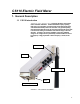
CS110 Electric Field Meter 1. General Description 1.1 CS110 Introduction Atmospheric electric fields have been measured easured for decades by electric field meters nicknamed “field mills”. Traditional field mills employ a spinning metal rotor (vane) electrically connected to Earth ground, placed between the external field and stationary metal sense electrodes.
CS110 Electric Field Meter Unlike traditional rotating vane field mills, the CS110 uses a reciprocating shutter. A stepper motor opens and then closes the reciprocating shutter by 45° during measurements. The reciprocating shutter is electrically connected to ground potential by a flexible stainless-steel strap operated below its fatigue limit, resulting in an ultra-reliable electrical ground connection.
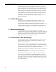
CS110 Electric Field Meter 1.5 Digital I/O Three general purpose 0 to 5 V digital I/O lines are available on the CS110 Power cable (CS110CBL3-L) that attaches to the circular power connector on the underside of the CS110. The blue, yellow, and green wires connect to control ports C1, C2, and C3 respectively. Using CRBasic, these digital I/O lines can be used to conditionally turn on alarms, provide an interrupt or pulsed signal to be measured by the CS110, or as a serial communication port. 1.
CS110 Electric Field Meter 2. CS110 Specifications Electric Field Measurement Performance: Parallel-Plate Configuration ±1% of reading + 60 V m-1 offset1 Accuracy Measurement Range3 (V m-1) Resolution (V m-1) Sensitivity (µV/V m1 ) Noise (V m-1 RMS) ±(0 to 21,000) 3 12 4.0 ±(21,000 to 212,000) 30 118 18.0 2 m CM10 Tripod Configuration2 Accuracy ±5% of reading + 8 V m-1 offset1 Resolution (V m-1) Sensitivity (µV/V m1 ) Noise (V m-1 RMS) ±(0 to 2,200) 0.32 1.2 0.42 ±(2,200 to 22,300) 3.
CS110 Electric Field Meter Sample (Measurement) Rate: Programmable sample rate up to 5 samples per second, variable sample rates possible. Variable example: sample every 10 seconds until field exceeds threshold then sample once a second until field returns to normal. Power Requirements: 11 to 16 Vdc; peak-current demand is 750 mA during motor operation. 7 mA @ 12 V = 0.08 W average power consumption at 1 sample per 10 seconds 60 mA @ 12 V = 0.
CS110 Electric Field Meter 6 Rugged Construction: Ultra-reliable metallic ground connection to reciprocating shutter (no wiping contact), brushless stepper motor, powder-coated aluminum case, Teflon insulators, and electro-polished 316L stainless steel used for corrosion protection of critical exposed metallic parts Easy Maintenance: The stator is easily removed for cleaning (proper cleaning does not invalidate calibration).
CS110 Electric Field Meter 3. CS110 Measurement Details The charge amplifier circuitry of the reciprocating electric field meter is depicted in Figure 2. Induced charge on the sense electrode results in the operational amplifier placing charge on the feedback capacitor C in order to restore the sense electrode to virtual ground. FIGURE 2.
CS110 Electric Field Meter 160 FIGURE 3. Charge amplifier output during an electric field measurement cycle Offset voltages Voff1 and Voff2 are zero field reference measurements made when the shutter is closed, and utilized to accurately estimate voltage ΔV when the shutter is completely open. Electronic offset voltages, surface potentials between various metallic parts and leakage currents on the charge amplifier input result in non-zero values of Voff1 and Voff2.
CS110 Electric Field Meter Ileak = Cf·(Voff1 – Voff2)/ΔT + Icomp (eq. 2) Where Cf is the value of feedback capacitor used in the charge amplifier, and Icomp is the leakage current compensation value implemented during the measurement. This charge amplifier input leakage current increases with degradation of insulation of the sense electrode insulators due to moisture or other surface contamination.
CS110 Electric Field Meter Average Current (mA) @ 12 V 1000 100 10 1 0.1 1 10 100 Measurement Interval (Seconds) FIGURE 4. CS110 average current consumption versus measurement interval The CS110 requires 11 V to 16 Vdc with a peak current demand of 750 mA during motor operation. The CS110 Power Cable (pn 16965) is used to connect the dc power supply to the CS110. The recommended maximum length on the CS110 Power Cable (CS110CBL3-L) is 50 feet.
CS110 Electric Field Meter CS110 CS I/O cable (CS110CBL2-L). Examples of CS I/O peripherals include the CR1000 Keyboard Display and the COM220 phone modem. The CS110 also offers SDI-12 communication or SDM (Synchronous Device for Measurement) control capability utilizing the CR1000 control ports available through the CS110 POWER CABLE (CS110CBL3-L). 4.4 Site Recommendations Many factors can distort and/or change the electric field at a given sight.
CS110 Electric Field Meter minimize non-ideal fringing effects. Sharp corners were avoided in order to prevent corona discharge. All metal parts of the calibrator are manufactured from stainless steel, and the inside surfaces are polished to reduce the surface charges in order to provide a stable zero electric field. All outer surfaces are electrically connected and tied to Earth ground while the insulated inner plate is driven by a high voltage amplifier.
CS110 Electric Field Meter of variations in surface cleanliness along with charging and discharging processes. Polished 316-L stainless-steel is used for critical electrode surfaces on the CS110 to minimize unwanted surface charges. CS110s with clean electrodes have been found to display electric field offsets <⏐30 V/m⏐, which has negligible effect on the determination of Mparallel_plate because of the ±15 kV/m range of electric fields used during factory calibration.
CS110 Electric Field Meter FIGURE 7. NIST calibration certificate NOTE Careful removal and replacement of the stator on the CS110 does not invalidate the factory derived Mparallel_plate of a given unit. However, switching stators with another unit or accidentally bending the stator, shutter or sense electrodes invalidates the factory parallel-plate calibration because of possible electrode dimensional changes. 5.
CS110 Electric Field Meter Consequently, a downward facing and elevated configuration as illustrated in Figure 8 is recommended for long-term field applications. FIGURE 8. CS110 2 Meter CM10 Tripod Site Inverting the CS110 reduces the effective gain while elevating it’s height above ground enhances the gain, with respect to an ideal upward-facing flushmounted geometry. It should be mentioned that this gain enhancement reduces the effect of unwanted electrical field offsets.
CS110 Electric Field Meter FIGURE 9. Campbell Scientific, Inc.
CS110 Electric Field Meter An upward-facing calibration kit (PN: 17579) was developed to hold the CS110 in a flush-mounted upward-facing position, as illustrated in Figure 10. FIGURE 10. CS110 attached to upward-facing flush-mounted plate for site correction NOTE Both the upward-facing and the inverted and elevated unit need to be electrically connected to Earth potential.
CS110 Electric Field Meter utilized to autonomously measure, process and store data to aid in site correction. Campbell Scientific, Inc. has performed a site correction on the CS110 2 Meter CM10 Tripod Site described in Appendix G. The collected data between the upward-facing unit and a downward facing CS110 2 Meter CM10 Tripod Site is illustrated in Fig 10. A best-fit line computed from the data resulted in Csite = 0.
CS110 Electric Field Meter covering the stator with a clean Zero Electric Field Cover (PN: 17642). Fair weather field site correction is not recommended for lightning warning applications because of the relatively poor accuracy in determining Csite. 6. Lightning Warning Lightning warning devices fall into two classes: lightning detectors and electric field monitors. Stand-alone lightning detectors provide warning based on nearby discharges, but give no warning until a detectable discharge occurs.
CS110 Electric Field Meter August 2, 2005 Thunderstorm at Logan, Utah 9000 8000 7000 6000 Electric Field (volt/meter) 5000 4000 3000 2000 1000 0 5:34:00 -1000 5:40:00 5:46:00 5:52:00 5:58:00 6:04:00 6:10:00 6:16:00 6:22:00 6:28:00 6:34:00 6:40:00 6:46:00 -2000 -3000 -4000 -5000 Mountain Standard Time (1 sample per second) FIGURE 12.
CS110 Electric Field Meter A network or array of electric field meters improves lightning warning because of a wider area of coverage along with measurement redundancy. The PackBusTM communication protocol capability of the CR1000 datalogger embedded in the CS110 provides for extensive networking capability. 7. CRBasic Programming The CR1000 uses a programming language that has similarities to structured BASIC, hence the name CRBasic.
CS110 Electric Field Meter Public variables are defined and available for viewing in the Public table, which is a data table automatically set up by the CR1000. The Public table keeps only the current value of each of the defined variables. In the example program, the DataTable instruction is used to define the data table Tab1. A record in a table consists of the data from all output processing instructions, along with a record number and time stamp data.
CS110 Electric Field Meter Units wind_speed=mph Public wind_dir Units wind_dir=deg Public solar_rad Units solar_rad=W/m2 Public air_temp Units air_temp=DegF Public RH Units RH=% Public internal_RH Units internal_RH=% Public E_status(16) Public k Public meas_error Public Error_Count 'E_field status array. 'Index for E_status array. 'Disable variable for slow table. 'Keep track of total errors measurements. DataTable(Tabslow,1,-1) '-1 to auto-allocate all available memory.
CS110 Electric Field Meter Scan(1,sec,0,0) for k = 1 to 16 'Initialize status array. E_status(k) = 0 next PanelTemp (panel_temp,250) Battery (battery_volt) VoltDiff (internal_RH,1,mV2500,5,True ,0,250,0.1,0) PulseCount (rain_fall,1,2,2,0,0.01,0) 'TE525 tipping bucket 0.01 inches per tip PulseCount (wind_speed,1,1 ,1,1,0.2192,0) 'Mult for 05103 Wind Monitor. BrHalf (wind_dir,1,mV2500,4,Vx2,1,2500,False,450,250,355,0) 'Mult. for 05103 Wind Monitor.
CS110 Electric Field Meter accomplished using a disable variable (DisableVar) associated with appropriate output processing instructions. The last parameter of the Average instruction is the DisableVar and will exclude the current measured value when DisableVar is not equal to zero.
CS110 Electric Field Meter Single-ended voltage measurements are referenced to ground, rather than the low side of a differential input. The VoltSE single-ended measurement instruction is quite similar to the VoltDiff instruction and is given as follows: VoltSe (Dest,Reps,Range,SEChan,MeasOff,Settling Time,Integ,Mult,Offset) An internal ground reference is utilized in single-ended measurements.
CS110 Electric Field Meter determine if results are returned as counts for a given interval (POption = 0), or as frequency = counts/(scan interval in seconds) (POption = 1). 8.2 Measuring Electric Field The CS110 instruction is used to perform the electric field measurement of the CS110 and follows: CS110(Dest,Leakage,Status,Integ,Mult,Offset) Leakage is a variable containing the measured leakage current in nano amps (nA) on the charge amplifier input during the CS110 electric field measurement.
CS110 Electric Field Meter purchased and connected to the SOLAR RADIATION connector to interface to either the CS100 or the CS106 barometric pressure sensor. Examples of instructions to measure the LI200X solar radiation sensor or the barometric pressure sensors are given below. ‘Measure LI200X. VoltDiff (solar_rad,1,mV7_5,3,True,450,250,200,0) ‘Measure CS106 - “continuous” or “always on” mode = jumper installed VoltDiff (Barom_pres,1,mV2500,3,True,450,250,0.
CS110 Electric Field Meter 8.7 Measuring Rainfall Circular connector labeled RAIN can be used to connect up a rain gauge using a switch closure such as the CS700 or the TE525MM tipping bucket rain gauges. Example CRBasic instruction to measure the TE525 is given below. PulseCount(rain_fall,1,2,2,0,0.01,0) 'TE525 tipping bucket 0.01 inches per tip 8.
CS110 Electric Field Meter default PakBus address of 1.
CS110 Electric Field Meter Remember to click on the “Apply” button to cause the settings to take effect. The “Apply” button is grayed out once it has been executed. Once this is done, switch to the “Connect” button on the LoggerNet Tool Bar, select the CS110, and select “Connect”.
CS110 Electric Field Meter If the connection is made and the stations time shows up in the window, you can then select the “Numeric:” button and add the desired public variables to see electric field readings updated every measurement interval. If you have changed the CR1000’s PakBus address and subsequently forgotten it, you can download from http://www.campbellsci.com/downloads at no cost, a software package named Device Configuration Utility that will discover the PakBus address.
CS110 Electric Field Meter 10. Maintenance 10.1 Checking Site Ground Integrity The CS110 electric field meter needs to be electrically connected to Earth ground for valid measurements. It is recommended that the integrity of this Earth Ground connection be checked periodically by verifying that the resistance of the stator to Earth Ground rod is <1 Ω. 10.2 Corrosion and Rust Inhibitors In corrosive environments, metal friction points (set screws, bolts, etc.
CS110 Electric Field Meter power electronics to high voltage switchgear. NO-OX-ID A-SPECIAL prevents the formation of oxides, sulfides and other corrosion deposits on copper surfaces and conductors can be prevented with its use.” Loctite also makes a similar product and some information on their products may be found at http://content.loctite.com/sticks/silver-as.html.
CS110 Electric Field Meter • Turbine studs • Coal crushers • Casting and Molding equipment • Heat exchangers 10.3 Self-Check Features The CS110 has been designed to provide reliable electric field measurements and to simplify and minimize maintenance. Scheduled maintenance may not be required, as the CS110 incorporates extensive self-checking, and provides status information about each measurement. An example CS110 instruction follows.
CS110 Electric Field Meter 10.4 Cleaning the CS110 Electrode Head The CS110 motor assembly illustrating the 316-L stainless-steel stator, shutter, and sense electrode is illustrated in Figure 13. Insulator Base Plate Shutter Sense Electrode Stator FIGURE 13. CS110 stator, shutter and sense electrode Contamination of the polished stator, shutter, and sense electrode can result in unwanted surface charges that induce electric field offset errors in the measurement.
CS110 Electric Field Meter ±4.2 nA. Leakage current values in excess of ±4.2 nA can cause measurement errors and are indicated by status = 11. Cleaning of the CS110 electrodes and/or insulators is recommended if any of the following conditions occur: • When insulators are dry, and leakage current exceeds ± 4.2 nA as indicated by status = 11. • Visual evidence of contamination (salt deposits, scaling, dust, spider webs etc.) on or around electrode area.
CS110 Electric Field Meter VoltDiff(Internal_RH,1,mV2500,5,True,0,250,0.1,0) 'Internal humidity measure. Changing of CS110 desiccant is recommended for internal relative humidity values ≥80%. FIGURE 14. Inside of CS110 case illustrating bracket for holding desiccant NOTE Replacement intervals less than once every six months for the 4 Unit (PN: 4905) desiccant pack within the sealed CS110 case indicate a problem with the CS110 case seal or with the desiccant packs being used.
CS110 Electric Field Meter 2. Inspect the gasket on the CS110 lid making sure that a good seal is possible when the lid is replaced. 3. Remove the old desiccant pack and replace with a new 4 unit desiccant pack (PN: 4905) making sure the new pack is placed into the bracket that prevents the desiccant from sliding into the motor assembly. 10.6 Checking Shutter/Encoder Alignment Status codes 14, 15, and 16 indicate problems with the stepper motor correctly opening and closing the shutter.
CS110 Electric Field Meter 10.7 Re-Calibration Re-calibration of measurement instruments is commonly done in data critical applications in order to combat component drift with time. Component drift is a function of the environment experienced by the instrument. High humidity and/or high temperature environments generally cause the most drift.
Appendix A. CS110 Measurement Status Codes Status codes 1 through 3: Good Instrument Health. status = 1, Good instrument health. ±250 mV measurement range only. Return measured Efield value. status = 2, Good instrument health. ±2500 mV measurement range used. Return measured Efield value. status = 3, Good instrument health. NAN returned for Efield because of measurement over-range on the ±2500 mV measurement range.
Appendix A. CS110 Measurement Status Codes Status codes 11 through 16: Measurement warnings and errors. status = 11, Leakage current exceeds compensation range of ± 4.2 nA. Return measured Efield value. status = 12 Failed charge-amplifier self check. Return NAN instead of measured Efield value. status = 13, Large closed shutter offset voltage. Vos > ⏐1.00 V⏐. Return NAN instead of measured Efield value. status = 14, Motor move error. Incorrect number of motor steps to close shutter.
Appendix B. CS110 Accessories B.1 Zero Electric Field Cover As previously mentioned, unwanted surface charges residing on nonconductive deposits on electrodes result in a non-zero electric field, even when external electric fields are zero. Polished 316-L stainless-steel is used for critical electrode surfaces on the CS110 to minimize unwanted surface charges. CS110’s with clean electrodes have been found to display electric field offsets less than 20 V/m in absolute value.
Appendix B.
Appendix C. CS110 Connector Pin-outs The following information describes the connectors that mate with the built-in (bulkhead) connectors on the CS110. Connector pin numbering for the 6 and 9 pin connectors are shown below. The view is a view of the solder-cup side of the cabled connector. The circular connectors are Mini-Con-X type from Conxall. The CSI part numbers shown for the connectors include the backshell. CSI fills the backshell with a relatively thick epoxy to seal and provide strain relief.
Appendix C. CS110 Connector Pin-outs RAIN CONNECTOR Connector is male and is CSI PN 9889 (Conxall #6282-6PG-522 or Switchcraft #EN3C6M). Pin 1 is indicated w/ a dot Pin 1 2 3 4 5 6 Description empty empty P2 empty Gnd Gnd Color Pulse channel 2 Power ground Power ground CSIO CONNECTOR CS110CBL2-L CS110 CS I/O Cable Connector is 9 pin female and is CSI PN 17674 (Conxall #3082-9SG-330).
Appendix C. CS110 Connector Pin-outs SOLAR RADIATION CONNECTOR Connector is male and is CSI PN 9889 (Conxall #6282-6PG-522 or Switchcraft #EN3C6M).
Appendix C.
Appendix D. Servicing the CS110 The CS110 has been designed to provide reliable electric field measurements and to simplify and minimize maintenance. An exploded view illustrating the various major components of the CS110 is illustrated in Figure D-1. Desiccant Holder Bracket Case Lid Interface Plate CS110 Panel Board Lid gasket CR1000 Datalogger CS110 Case Motor Assembly FIGURE D-1. Exploded view of CS110 Electric Field Meter D.
Appendix D. Servicing the CS110 CS110 panel board, after removing the two thumb screws on the CR1000 module. When installing a CR1000 into the CS110 case, first check for proper orientation of the three 40-pin connectors that interface to the CS110 panel board. Once proper connector orientation is verified, set the CR1000 into the CS110 case and feel for proper positioning of the three 40-pin connectors.
Appendix D. Servicing the CS110 D.5 Shutter/Encoder Alignment A factory trim is done to align the position of the CS110 shutter with an Index mark on the rotary position encoder. Re-trimming of the shutter/encoder alignment becomes necessary after encoder disassembly. The procedure to trim the shutter/encoder alignment uses a CS110 single-step trim instruction called CS110Trim. This instruction allows a single shutter step open (flag 1) and closed (flag 2) utilizing the flag capability in LoggerNet.
Appendix D. Servicing the CS110 EndIf If Flag(2) Then CS110Trim(-1) Flag(2) = 0 EndIf NextScan EndProg 'Take a step closed. 'Reset Flag 2. The CS110_Index_Trim.cr1 program uses flags 1, 2 and 3 available in LoggerNet, for user control. Flags 1 and 2 are used to single step the shutter one step open and closed, respectively. These flags are used initially to position the shutter into the fully opened position, as observed visually by stator to shutter overlap.
Appendix D. Servicing the CS110 Connector Locking Plate Motion of Encoder Base Plate Encoder Base Plate FIGURE D-2. CS110 motor assembly Referring to Figure D-2, loosen the 2 Philips head screws on the connector locking plate on the top of the motor assembly. Slowly rotate the encoder base plate until Index (Control Port # 8) always equals 5 V (5 V = True = Green in LoggerNet). Tighten down the 2 Philips head screws on the connector locking plate and verify that Index still equals 5 V.
Appendix D. Servicing the CS110 'Program to open/close the CS110 shutter (CS110_Shutter1.cr1). 'Last updated by Jody Swenson on 9/26/05. Public PTemp Public Batt Public stat(2) DataTable(Efield,1,-1) Sample(2,stat,FP2) Sample(1,PTemp,IEEE4) Sample(1,Batt,IEEE4) EndTable BeginProg Scan(5000,msec,0,0) PanelTemp(PTemp,250) Battery(Batt) CS110Shutter(stat(1),1) Delay (0,3000,mSec) CS110Shutter(stat(2),0) CallTable Efield NextScan EndProg 'Fully open shutter. 'Fully close shutter. D.
Appendix E. CS110 as a Slow Antenna As previously mentioned the CS110 can sample the external electric field at a maximum rate of 5 Hz (200 ms) using the CS110 instruction. Faster sampling of the rapid electric field changes associated with lightning discharges is desirable in some applications, and can be accomplished with the CS110 electric field meter configured as a Slow Antenna which is sometimes called a field change meter. E.
Appendix E. CS110 as a Slow Antenna Overall Frequency Response of CS110 Slow-Antenna Measurement with 250 us Integration 1 0.999 Relative Magnitude 0.833 0.667 MagSys ( f ) 0.5 0.333 0.167 0 0 0.1 0.1 1 10 100 1 ×10 3 f Frequency (Hz) FIGURE E-1.
Appendix E. CS110 as a Slow Antenna E.2 Response of the CS110 Slow Antenna in the Time Domain The following graphs shows one lightning strike measured at 50 Hz by both the CS110 slow antenna and by one of Kennedy Space Center’s (KSC) field mills. In Figure E-3 the KSC electric field meter readings have been converted to efield change per measurement. FIGURE E-2.
Appendix E. CS110 as a Slow Antenna FIGURE E-3. KSC electric field change and CS110 slow antenna data The KSC electric field mill and the CS110 were not precisely synced accounting for some of the differences in the data shown in the above graph. Since that time, the CS110 has been improved and now has the ability to sync to within ±10 µs of the GPS signal’s PPS pulse.
Appendix E. CS110 as a Slow Antenna E.3 Programming The following CRBasic program utilizes the slow antenna capability of the CS110. 'Program to use the CS110 in slow antenna mode (slowant1.cr1). 'Last updated by Jody Swenson on 9/30/05.
Appendix E. CS110 as a Slow Antenna E.4 Calibration The factory calibration described in Section 5 applies to the maximum amplitude of the step response of the CS110 when it is operating as a slow antenna. Switching in the 200 MΩ resistor in the feedback path simply slows the decay of the signal induced on the sense electrode resulting in a 66 millisecond decay time constant The CS110 operating as a slow antenna returns the change in the electric field with units of volts per meter per scan.
Appendix F. Example CRBasic Programs An example CS110 weather station program using a variable electric field measurement rate in order to minimize current consumption in solar powered applications follows. 'CS110 efield and weather station program with variable measurement 'rate for low-power consumption.(CS110_low_power.cr1). 'Measures rainfall, wind speed and direction, solar radiation, 'relative humidity, air temperature, and electric field.
Appendix F. Example CRBasic Programs DataTable(Tabslow,1,-1) '-1 to auto-allocate all available memory. DataInterval(0,60,sec,10) 'Averaged 60 second output data. Average(1,E_field,ieee4,meas_error) Sample (1,run_Avg10,ieee4) Totalize (16,E_status,FP2,0) 'Look at Efield status array for last 60 seconds.
Appendix F. Example CRBasic Programs CS110(E_field,leakage_cur,status,_60Hz,Mcorrected,0) If E_field = NAN Then meas_error = 1 'Disable output to slow table if efield = NAN. E_field_int = FAST_INTERVAL 'Go to fast interval if NAN. EndIf E_status(status) = 1 'Set appropriate element in status array. Endif If E_field <> NAN Then AvgRun (run_avg10,1,E_field,10) 'Used for average output in fast table. AvgRun (abs_run_avg600,1,ABS(E_field),600) 'Used to stay longer at fast interval.
Appendix F.
Appendix G. CS110 2 Meter CM10 Tripod Site FIGURE G-1. CS110 2 Meter CM10 Tripod site The Tripod_CS110 site consists of the CS110 mounted on the CM10 Tripod at a height of 2 meters, and a 12 x 14 inch enclosure.
Appendix G. CS110 2 Meter CM10 Tripod Site Installation of the Tripod_CS110 Site: Drive the ground rod into the ground where the center of the tripod is to be placed. Extend the tripod legs so the far end of the sliding clamp is 56 inches (142 cm) from the mast end of the pipe. Extending the legs as described above puts the feet on a circle with a radius of approximately 77 inches (196 cm) from the center of the tripod to the outside edge of the pivoting feet.
Appendix G. CS110 2 Meter CM10 Tripod Site FIGURE G-2. CS110 on CM10 Tripod Mast Mount the fiberglass enclosure to the top of the leg facing the equator with the top bracket approximately 2 inches (5 cm) below the top of the leg. Be careful opening the lid because in this almost horizontal position it is possible to pull the hinge rivets out of the enclosure. If there is a solar panel, install the solar panel on the leg facing the equator below the enclosure.
Appendix G. CS110 2 Meter CM10 Tripod Site FIGURE G-3. Earth grounding Stake the tripod to the ground and/or weigh it down with sand bags. Determination of Csite Surface mounted upward facing CS110: SN1022 with Mparallel_plate = 87.6 Tripod with CS110 only: SN1023 with Mparallel_plate = 81.77 Each CS110 recorded one minute averages of 1 second measurements of electric field data for the same 2200 to 2300 hour time period on October 2, 2005. The data from both units is plotted in Figure G-4.
Appendix G. CS110 2 Meter CM10 Tripod Site Site Correction for Tripod CS110 Only Site - October 2, 2005 1 minute average of 1 second data Results indicate Csite = 0.105. Electric Field (volt/meter for Upward Facing CS110 SN:1022 Mparallel_plate = 87.6 volt/meter*millivolt 8000 6000 4000 y = 0.1051x - 35.664 R2 = 0.
Appendix G.
Appendix H. Tripod CS110 and StrikeGuard Site H.1 Tripod CS110 and StrikeGuard FIGURE H-1.
Appendix H. Tripod CS110 and StrikeGuard Site H.1.1 Installation of the Tripod CS110 and StrikeGuard Site Drive the ground rod into the ground where the center of the tripod is to be placed. Extend the tripod legs so the far end of the sliding clamp is 56 inches (142 cm) from the mast end of the pipe. Extending the legs as described above puts the feet on a circle with a radius of approximately 77 inches (196 cm) from the center of the tripod to the outside edge of the pivoting feet.
Appendix H. Tripod CS110 and StrikeGuard Site FIGURE H-2. CS110 and StrikeGuard on tripod mast Mount the fiberglass enclosure to the top of the leg facing the equator with the top bracket approximately 2 inches (5 cm) below the top of the leg. Be careful opening the lid because in this almost horizontal position it is possible to pull the hinge rivets out of the enclosure. If there is a solar panel, install the solar panel on the leg facing the equator below the enclosure.
Appendix H. Tripod CS110 and StrikeGuard Site FIGURE H-3.
Appendix H. Tripod CS110 and StrikeGuard Site FIGURE H-4. Grounding the tripod and battery Stake the tripod to the ground or weight it down with sand bags. Connect power and communication cables as shown in Figure H-5.
Appendix H. Tripod CS110 and StrikeGuard Site FIGURE H-5.
Appendix H. Tripod CS110 and StrikeGuard Site Power and communication cables should be run down the equator side of the mast and under the enclosure as shown. Wire-tie all cables into place so they don’t move with the wind. H.1.2 Determination of Csite Surface mounted upward facing CS110: SN1022 with Mparallel_plate = 88.31. CM10 Tripod Mounted StrikeGuard and CS110: SN1023 with Mparallel_plate = 81.77.
Appendix H.
Campbell Scientific Companies Campbell Scientific, Inc. (CSI) 815 West 1800 North Logan, Utah 84321 UNITED STATES www.campbellsci.com • info@campbellsci.com Campbell Scientific Africa Pty. Ltd. (CSAf) PO Box 2450 Somerset West 7129 SOUTH AFRICA www.csafrica.co.za • cleroux@csafrica.co.za Campbell Scientific Australia Pty. Ltd. (CSA) PO Box 8108 Garbutt Post Shop QLD 4814 AUSTRALIA www.campbellsci.com.au • info@campbellsci.com.au Campbell Scientific do Brazil Ltda.