INSTRUCTION MANUAL CM3 Pyranometer Revision: 10/02 C o p y r i g h t ( c ) 1 9 9 9 - 2 0 0 2 C a m p b e l l S c i e n t i f i c , I n c .
Warranty and Assistance The CM3 PYRANOMETER is warranted by CAMPBELL SCIENTIFIC, INC. to be free from defects in materials and workmanship under normal use and service for twelve (12) months from date of shipment unless specified otherwise. Batteries have no warranty. CAMPBELL SCIENTIFIC, INC.'s obligation under this warranty is limited to repairing or replacing (at CAMPBELL SCIENTIFIC, INC.'s option) defective products.
CM3 Pyranometer Table of Contents PDF viewers note: These page numbers refer to the printed version of this document. Use the Adobe Acrobat® bookmarks tab for links to specific sections. 1. General Description....................................................1 2. Specifications .............................................................1 3. Installation...................................................................2 4. Wiring .........................................................................
This is a blank page.
CM3 Pyranometer 1. General Description This manual provides information for interfacing Kipp & Zonen’s CM3 Pyranometer to a CR10(X), CR510, CR23X, CR7 or 21X datalogger. The CM3 is shipped with an instruction manual provided by Kipp & Zonen that contains information concerning the CM3’s construction, spectral sensitivity, cosine response, and a simple sensor check out procedure. Included with the sensor and manual is a calibration certificate with the sensor calibration constant and serial number.
CM3 Pyranometer Temperature Dependence of sensitivity: + 6% (-10 to + 40ºC) 2 Tilt response (+80º) (at 1000 W/m ): < + 2% OTHER SPECIFICATIONS Expected accuracy for daily sums: + 10% Spectral range (50% points, nm): 305-2800 nm Sensitivity: 10 - 35 µV/Wm-2 Expected signal output in atmospheric application: 0 - 50 mV Impedance: 79 - 200 (Ω) Operating Temperature: -40 to +80ºC Max.
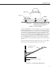
CM3 Pyranometer CM3 Sensor Bubble Level CM3MT PN7790(3) 015 Pyranometer Mounting Arm or 025 Pyranometer Crossarm Stand FIGURE 3-1. CM3 and CM3MT Install the CM3MT Mount on either the 025 Pyranometer Cross Arm Stand, the 015 Pyranometer Mounting Arm, or the UTKZ (not yet available, please call) before mounting them to the tower or tripod. This is done by first threading the screws through the springs and just barely through the mounting plate.
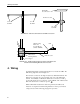
CM3 Pyranometer 025STAND Crossarm Stand 019ALU Crossarm 3/4” x 3/4” NU-RAIL 3/4” x 1” NU-RAIL 3/4” x 3/4” NU-RAIL FIGURE 3-3. 025 Crossarm Stand and 019ALU Crossarm UTKZ Leveling Fixture and Crossarm Mount (includes CM3MT) UT018 Tower Mounting Bracket CM3 UT018 Crossarm Tower Support FIGURE 3-4. UTKZ Leveling Fixture and Crossarm Mount and UT018 Tower Mounting Bracket and Crossarm 4. Wiring Use Differential Voltage measurement instruction 2 to measure the CM3.
CM3 Pyranometer If a 21X is used to measure the CM3 and it powers a 12 VDC sensor or 12 VDC radio, the current drawn off the 12 VDC supply may cause a difference in ground potential between the 21X ground terminals and the reference ground point in the datalogger. This ground potential results in an offset on single ended measurements. This offset can be as large as +60 mV. Thus, single ended measurements should be avoided. The offset does not, however, affect differential measurements.
CM3 Pyranometer 5. Example Programs Solar radiation can be reported as an average flux density (W m-2) or daily total flux density (MJ m-2). The appropriate multipliers are listed in Table 5-1. Programming examples are given for both average and daily total solar radiation. The output from the CM3 varies from 10-35 x 10-6V / W m-2. Given a maximum solar radiation of 1500 W m-2, the maximum sensor output voltage will be 15 - 52.5 mV. Example: (21.87 x 10⁻⁶ V W-1m2) ∗ (1500 W m-2) = 0.03281 V or 32.
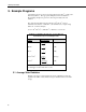
CM3 Pyranometer Example 1 ;{CR10X} ; *Table 1 Program 01: 10 Execution Interval (seconds) 1: Volt (Diff) (P2) 1: 1 2: 24 3: 1 4: 1 5: 45.725 6: 0.0 Reps 250 mV 60 Hz Rejection Range DIFF Channel Loc [ W_m2 ] Mult ;multiplier = (1 / 0.02187 mV / W/m2) Offset ;Set negative values to zero. ; 2: If (X<=>F) (P89) 1: 1 X Loc [ W_m2 2: 4 < 3: 0 F 4: 30 Then Do ] 3: Z=F x 10^n (P30) 1: 0.
CM3 Pyranometer 5.2.1 Output Format Considerations If the solar radiation is totalized in units of kJ m-2, there is a possibility of over-ranging the output limits. The largest number that the datalogger can output to final storage is 6999 in low resolution and 99999 in high resolution (Instruction 78, Set Resolution). Assume that the daily total flux density is desired in kJ m-2. Assume an irradiance of 0.5 kW m-2, the maximum low-resolution output limit will be exceeded in just under four hours.
CM3 Pyranometer 4: Z=F x 10^n (P30) 1: 0.0 F 2: 00 n, Exponent of 10 3: 1 Z Loc [ MJ_m2____ ] 5: End (P95) 6: If time is (P92) 1: 0 Minutes (Seconds --) into a 2: 60 Interval (same units as above) 3: 10 Set Output Flag High (Flag 0) 7: Real Time (P77) 1: 1220 Year,Day,Hour/Minute (midnight = 2400) 8: Totalize (P72) 1: 1 Reps 2: 1 Loc [ MJ_m2____ ] *Table 2 Program 02: 0.0000 Execution Interval (seconds) *Table 3 Subroutines End Program 6.
CM3 Pyranometer This is a blank page.
This is a blank page.
Campbell Scientific Companies Campbell Scientific, Inc. (CSI) 815 West 1800 North Logan, Utah 84321 UNITED STATES www.campbellsci.com info@campbellsci.com Campbell Scientific Africa Pty. Ltd. (CSAf) PO Box 2450 Somerset West 7129 SOUTH AFRICA www.csafrica.co.za sales@csafrica.co.za Campbell Scientific Australia Pty. Ltd. (CSA) PO Box 444 Thuringowa Central QLD 4812 AUSTRALIA www.campbellsci.com.au info@campbellsci.com.au Campbell Scientific do Brazil Ltda.