
User Manual


A150 Desiccated Case
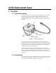
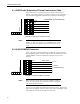
It is not recommended to insert more than one wire into each
connection on the terminal block. If it is necessary to combine
wires, use the 5-position lever nut to combine the wires, and then
insert the lead wire from the lever nut into the terminal block.
NOTE
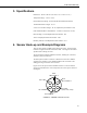
When used with a CWS900, the sensor can be used with sensors measuring
analog voltages, frequency, and pulse. The CWS900 can also provide
excitation voltage to a sensor through the A150.
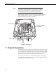
T
erminal Block
Lever Nut
Wire to Datalogger
or CWS900
Vent
FIGURE 2. A150 Interior
2. Physical Description
The A150 has an 80 mm x 82 mm x 55 mm chassis. Four screws secure the lid
to the rest of the unit. A terminal block is mounted inside the chassis. A small
vent is located on the bottom of the chassis. The vent is protected by a GORE
®
filter, which prevents moisture and contaminants from entering the unit while
equalizing the interior air pressure to the current atmospheric pressure.
A mounting bracket is attached to the bottom of the chassis. The bracket is
used to fasten the A150 inside an enclosure or, with the included Velcro
®
strap,
to another location of the user’s choosing.
2