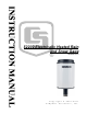
52202 Electrically Heated Rain and Snow Gage Revision: 5/11 C o p y r i g h t © 2 0 1 0 - 2 0 1 1 C a m p b e l l S c i e n t i f i c , I n c .
Warranty and Assistance PRODUCTS MANUFACTURED BY CAMPBELL SCIENTIFIC, INC. are warranted by Campbell Scientific, Inc. (“Campbell”) to be free from defects in materials and workmanship under normal use and service for twelve (12) months from date of shipment unless otherwise specified on the corresponding Campbell invoice. Batteries, fine-wire thermocouples, desiccant, and other consumables have no warranty.
52202 Table of Contents PDF viewers note: These page numbers refer to the printed version of this document. Use the Adobe Acrobat® bookmarks tab for links to specific sections. 1. General Description.....................................................1 2. Specifications ..............................................................1 3. Installation....................................................................2 3.1 Siting................................................................................
2202 Electrically Heated Rain and Snow Gage 1. General Description RM Young’s Model 52202-L is an electrically heated precipitation gage that provides year-round measurement of rain or snow. This gage requires a reliable source of 24 Vac power. It includes a wall transformer that plugs into a wall socket and provides 24 Vac. Output is a switch closure for each bucket tip. A –L after the model number indicates that the cable length is specified when ordering.
52202 Electrically Heated Rain and Snow Gage 3. Installation NOTE The 260-953 Alter-Type Wind Screen’s siting information and installation procedure are provided in the 260-953 manual. 3.1 Siting The 52202 should be mounted in a relatively level spot which is representative of the surrounding area. The lip of the funnel should be horizontal and at least 30 cm. above the ground. It should be high enough to be above the average snow depth.
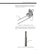
52202 Electrically Heated Rain and Snow Gage The pipe attaches to a CM202, CM204, or CM206 crossarm via a CM220 Right Angle Mounting Bracket (see Figure 3-2). The crossarm attaches to a tripod mast, tower leg, CM300-series mounting pole, or a user-supplied vertical pipe (1.0-in. to 2.1-in. OD). Crossarm CM220 FIGURE 3-2. The CM220 Mounted to a Crossarm Alternatively, the 3659 pipe can be attached to the top of our stainless-steel tripods via the CM216 Sensor Mounting Kit. The CM216 extends 4-in.
52202 Electrically Heated Rain and Snow Gage After mounting the 52202, level the gage and remove the shipping retainer by performing the following procedure: 1. Loosen the three screws that retain housing to base assembly (see Figure 3-1). Carefully lift housing free of base. 2. Remove shipping retainer from bucket. Verify that bucket tips freely. 3. Adjust leveling screws until bulls eye level is centered. 4. Replace housing and retighten screws. 4.
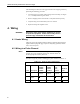
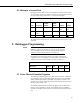
52202 Electrically Heated Rain and Snow Gage 4.3 Wiring to a Control Port Dataloggers listed in Table 4-2 have the capability of counting switch closures on some of their control ports. When a control port is used, the return from the rain gage switch must be connected to +5 volts on the datalogger. TABLE 4-2.
52202 Electrically Heated Rain and Snow Gage 5.1.1 CR1000 Example Program 'CR1000 'RM_Young Tipping Blk > P1 ' Wht > ground 'Cabling for heater goes to 24VAC power supply Public Rain_mm Units Rain_mm=mm DataTable(Rain,True,-1) DataInterval(0,60,Min,0) Totalize(1,Rain_mm,FP2,0) EndTable BeginProg Scan(1,Sec,1,0) PulseCount(Rain_mm,1,1,2,0,0.1,0) CallTable(Rain) NextScan EndProg 5.1.
52202 Electrically Heated Rain and Snow Gage 5.1.3 CR10X Example Program ;{CR10X} *Table 1 Program 01: 1.0000 Execution Interval (seconds) 1: Pulse (P3) 1: 1 2: 1 3: 2 4: 3 5: 0.
52202 Electrically Heated Rain and Snow Gage 5.2.
52202 Electrically Heated Rain and Snow Gage 5.2.2 CR10X Example Program ;{CR10X} ; *Table 1 Program 01: 1 Execution Interval (seconds) 1: Pulse (P3) 1: 1 2: 8 3: 2 4: 1 5. 0.
52202 Electrically Heated Rain and Snow Gage 3. Disconnect the sensor from the datalogger and use an ohm meter to do a continuity check of the switch. The resistance measured at the terminal block on the inside of the bucket between the black and white leads should vary from infinite (switch open) when the bucket is tipped, to less than an ohm when the bucket is balanced. 7. Maintenance The rain gage should be inspected periodically.
Campbell Scientific Companies Campbell Scientific, Inc. (CSI) 815 West 1800 North Logan, Utah 84321 UNITED STATES www.campbellsci.com • info@campbellsci.com Campbell Scientific Africa Pty. Ltd. (CSAf) PO Box 2450 Somerset West 7129 SOUTH AFRICA www.csafrica.co.za • cleroux@csafrica.co.za Campbell Scientific Australia Pty. Ltd. (CSA) PO Box 444 Thuringowa Central QLD 4812 AUSTRALIA www.campbellsci.com.au • info@campbellsci.com.au Campbell Scientific do Brazil Ltda.