
Manual

4WFBS120, 4WFBS350, 4WFBS1K 4 Wire Full Bridge Terminal Input Modules (TIM)
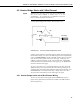
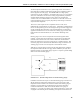
4.4.1.1 Mathematical Lead Compensation Circuit and Equations
If the lead resistance is known, the sensitivity error can be mathematically
corrected for by multiplying the output by a simple factor (1+R
L
/R
G
) where R
L
is the nominal resistance of one of the lead legs and R
G
is the resistance of the
strain gauge. The Gauge Factor can be multiplied by the inverse of this value,
R
G
/(R
G
+ R
L
), to derive an adjusted Gauge Factor.
⎟
⎟
⎞
⎜
⎜
⎛
×=
g
rawadj
R
GFGF
⎠⎝
+
Lg
RR
4.4.1
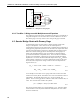
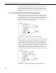
The adjusted Gauge Factor, GF
adj
, would be used in the StrainCalc function to
derive the µ
Strain. The proof used to derive this adjusted Gauge Factor is
shown below:
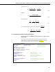
R
2
= 1KΩ
R
1
= 1KΩ
R
D
R
L
R
L
R
4
=Gauge
Excite
+
-
R
L
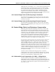
FIGURE 4.4-1. Three wire ¼ bridge strain circuit
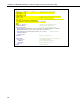
Balanced Bridge Condition
21
1
L
DLG
LG
BAL
I
O
RR
R
RRRR
RR
E
E
+
−
+++
+
=
⎟
⎟
⎠
⎞
⎜
⎜
⎝
⎛
4.4.2
Strained Bridge Condition
21
1
G
LDLG
GLG
STR
I
O
RR
R
RRRRR
RRR
E
E
+
−
Δ++++
Δ++
=
⎟
⎟
⎠
⎞
⎜
⎜
⎝
⎛
4.4.3
Change in Bridge Output (V
R
)
LGD
LG
G
GLD
GLG
BAL
I
O
STR
I
O
R
2RRR
RR
RR2RR
RRR
E
E
E
E
V
++
+
−
Δ+++
Δ++
=
⎟
⎟
⎠
⎞
⎜
⎜
⎝
⎛
−
⎟
⎟
⎠
⎞
⎜
⎜
⎝
⎛
=
4.4.4
22