
Manual
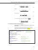

4WFBS120, 4WFBS350, 4WFBS1K 4 Wire Full Bridge Terminal Input Modules (TIM)
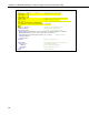
6: Z=F (P30) ;Load Gage Factor into input location
1: 2 F ;Enter the actual Gage Factor here
2: 6 Z Loc [ GF ]
7: Z=X/Y (P38) ;calculate multiplier to use with strain
1: 7 X Loc [ 4e6 ] ;calculation
2: 6 Y Loc [ GF ]
3: 8 Z Loc [ Mult ]
8: Beginning of Loop (P87) ;Loop through 5 times to obtain average
1: 0 Delay ;zero reading
2: 5 Loop Count
9: Z=Z+1 (P32) ;Increment Counter used to determine
1: 5 Z Loc [ count ] ;when to output
10: Full Bridge (P6) ;Measure Strain Gage
1: 1 Reps
2: 2 ± 15 mV Slow Range
3: 1 DIFF Channel
4: 1 Excite all reps withExchan 1
5: 5000 mV Excitation
6: 1 Loc [ mVperV ]
7: 1 Mult
8: 0 Offset
11: IF (X<=>F) (P89) ;Check for last pass through loop
1: 5 X Loc [ count ] ;to set output flag
2: 3 >=
3: 5 F
4: 10 Set Output Flag High
12: Set Active Storage Area (P80) ;Direct averaged "zero" reading
1: 3 Input Storage ;to input storage
2: 2 Array ID or Loc [ mVperV_0 ]
13: Average (P71)
1: 1 Reps
2: 1 Loc [ mVperV ]
14: If Flag/Port (P91) ;When average is calculated,
1: 10 Do if Output Flag is High (Flag 0) ;also send it to Final Storage
2: 10 Set Output Flag High
15: Set Active Storage Area (P80) ;Direct Output to Final Storage
1: 1 Final Storage
2: 11 Array ID ;set Array ID = 11 for zero data
16: Real Time (P77)
1: 110 Day,Hour/Minute
17: Sample (P70)
1: 1 Reps
2: 2 Loc [ mVperV_0 ]
18: End (P95)
19: End (P95)
End Program
16